Introduction
1.1.3OSM ITP53
Possible Attachments
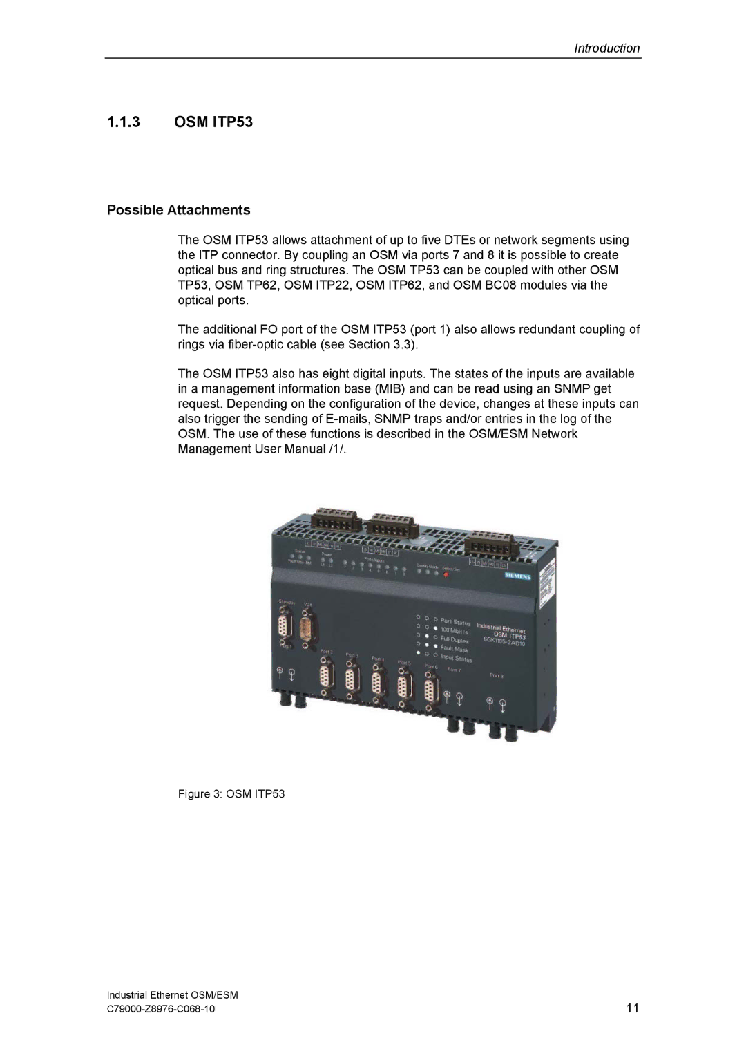
The OSM ITP53 allows attachment of up to five DTEs or network segments using the ITP connector. By coupling an OSM via ports 7 and 8 it is possible to create optical bus and ring structures. The OSM TP53 can be coupled with other OSM TP53, OSM TP62, OSM ITP22, OSM ITP62, and OSM BC08 modules via the optical ports.
The additional FO port of the OSM ITP53 (port 1) also allows redundant coupling of rings via
The OSM ITP53 also has eight digital inputs. The states of the inputs are available in a management information base (MIB) and can be read using an SNMP get request. Depending on the configuration of the device, changes at these inputs can also trigger the sending of
Figure 3: OSM ITP53
Industrial Ethernet OSM/ESM | 11 |