Installation | 4 |
BBU INSTALLATION INSTRUCTIONS
![]()
![]()
![]()
![]()
![]()
![]()
![]()
![]()
![]() Risk of electrical shock. At the circuit breaker or fuse box, turn off the electrical power to the sump pump before beginning this installation.
Risk of electrical shock. At the circuit breaker or fuse box, turn off the electrical power to the sump pump before beginning this installation.
Setup
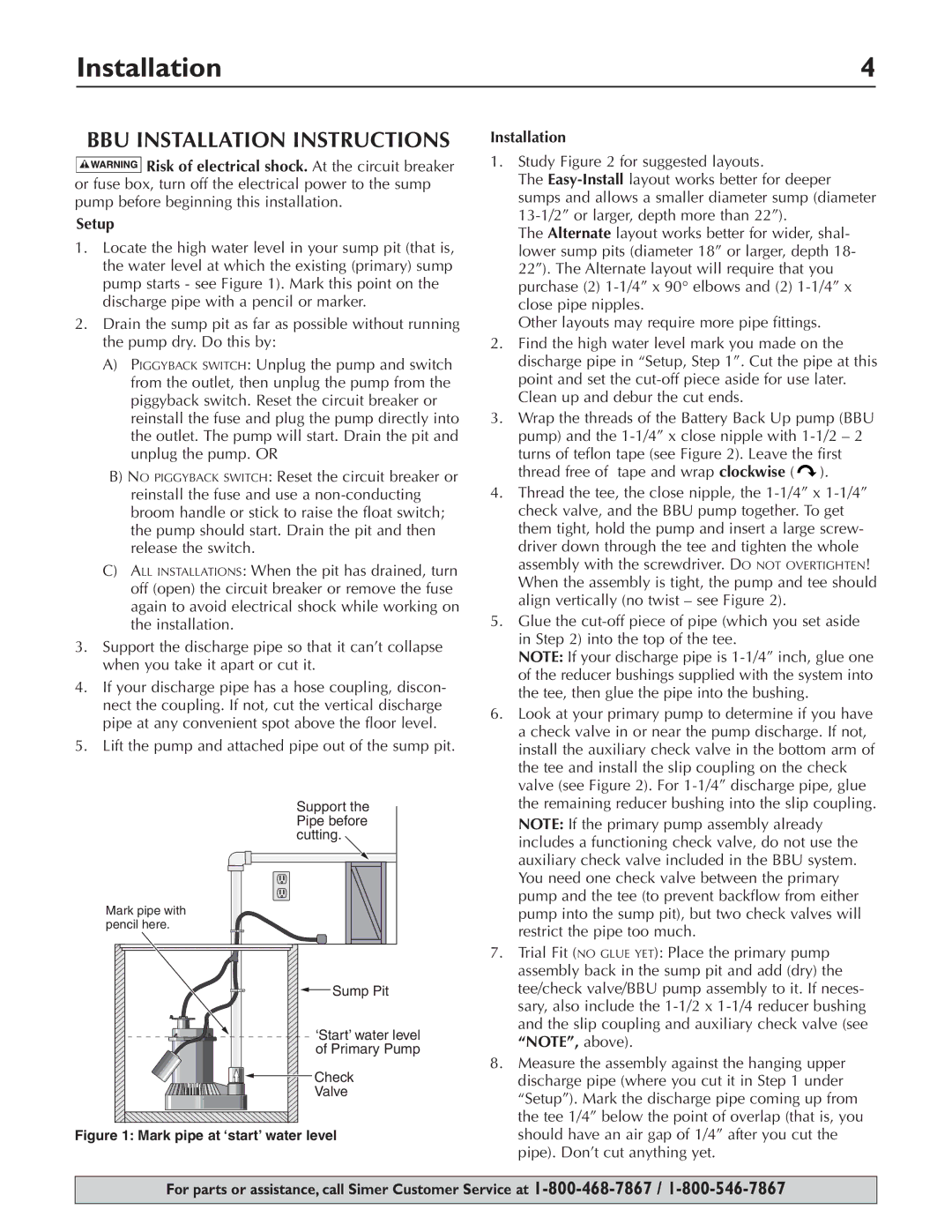
1.Locate the high water level in your sump pit (that is, the water level at which the existing (primary) sump pump starts - see Figure 1). Mark this point on the discharge pipe with a pencil or marker.
2.Drain the sump pit as far as possible without running the pump dry. Do this by:
A)PIGGYBACK SWITCH: Unplug the pump and switch from the outlet, then unplug the pump from the piggyback switch. Reset the circuit breaker or reinstall the fuse and plug the pump directly into the outlet. The pump will start. Drain the pit and unplug the pump. OR
B)NO PIGGYBACK SWITCH: Reset the circuit breaker or reinstall the fuse and use a
C)ALL INSTALLATIONS: When the pit has drained, turn off (open) the circuit breaker or remove the fuse again to avoid electrical shock while working on the installation.
3.Support the discharge pipe so that it can’t collapse when you take it apart or cut it.
4.If your discharge pipe has a hose coupling, discon- nect the coupling. If not, cut the vertical discharge pipe at any convenient spot above the floor level.
5.Lift the pump and attached pipe out of the sump pit.
Support the |
Pipe before |
cutting. |
Mark pipe with |
pencil here. |
Sump Pit |
‘Start’ water level |
of Primary Pump |
Check |
Valve |
Figure 1: Mark pipe at ‘start’ water level
Installation
1.Study Figure 2 for suggested layouts.
The
The Alternate layout works better for wider, shal- lower sump pits (diameter 18” or larger, depth 18- 22”). The Alternate layout will require that you purchase (2)
Other layouts may require more pipe fittings.
2.Find the high water level mark you made on the discharge pipe in “Setup, Step 1”. Cut the pipe at this point and set the
3.Wrap the threads of the Battery Back Up pump (BBU pump) and the ![]() ).
).
4.Thread the tee, the close nipple, the
5.Glue the
NOTE: If your discharge pipe is
6.Look at your primary pump to determine if you have a check valve in or near the pump discharge. If not, install the auxiliary check valve in the bottom arm of the tee and install the slip coupling on the check valve (see Figure 2). For
NOTE: If the primary pump assembly already includes a functioning check valve, do not use the auxiliary check valve included in the BBU system. You need one check valve between the primary pump and the tee (to prevent backflow from either pump into the sump pit), but two check valves will restrict the pipe too much.
7.Trial Fit (NO GLUE YET): Place the primary pump assembly back in the sump pit and add (dry) the tee/check valve/BBU pump assembly to it. If neces- sary, also include the
8.Measure the assembly against the hanging upper discharge pipe (where you cut it in Step 1 under “Setup”). Mark the discharge pipe coming up from the tee 1/4” below the point of overlap (that is, you should have an air gap of 1/4” after you cut the pipe). Don’t cut anything yet.
For parts or assistance, call Simer Customer Service at