Installation
•Use the fingers and turn clockwise until a noticeable increase in torque is required.
•Tighten further by 30 degrees (= 1/12 of a turn) using necessary force
Pumps with new fittings have got new serial no. code and is valid from the following s.no’s; RPU80: s.n. 2460 H06, RPU160: s.n. 1560 H14, RPU300: s.n. 380 H28, RPU300, 24V: s.n. 180 H29
| Installation of pipes |
| Drain the oil from the steering gear by loosening the rudder |
| cylinder couplings. At a convenient point cut the pipes and |
| mount a |
| appropriate diameter should be used. Ensure that the pipe is cut |
| at a right angle as otherwise the ultimate tightness of the |
| coupling may be adversely affected. It is preferable to use pipe |
| cutting tool for this operation. |
Note ! | It is very important to remove ALL traces of metal filings and |
| other impurities from the pipes after cutting. |
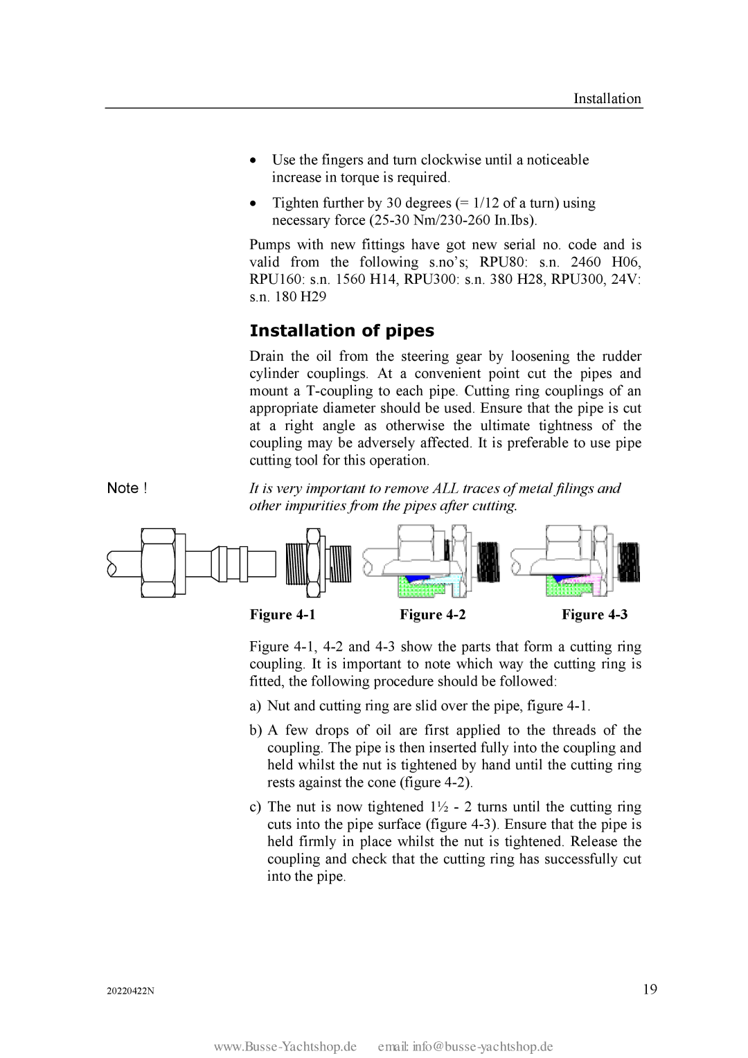
Figure | Figure | Figure |
Figure 4-1, 4-2 and 4-3 show the parts that form a cutting ring coupling. It is important to note which way the cutting ring is fitted, the following procedure should be followed:
a)Nut and cutting ring are slid over the pipe, figure 4-1.
b)A few drops of oil are first applied to the threads of the coupling. The pipe is then inserted fully into the coupling and held whilst the nut is tightened by hand until the cutting ring rests against the cone (figure 4-2).
c)The nut is now tightened 1½ - 2 turns until the cutting ring cuts into the pipe surface (figure 4-3). Ensure that the pipe is held firmly in place whilst the nut is tightened. Release the coupling and check that the cutting ring has successfully cut into the pipe.
20220422N | 19 |
