Simrad Reversible Pump RPU80/160/300
3 DESCRIPTION OF RPU80/RPU160/RPU300
3.1 Construction
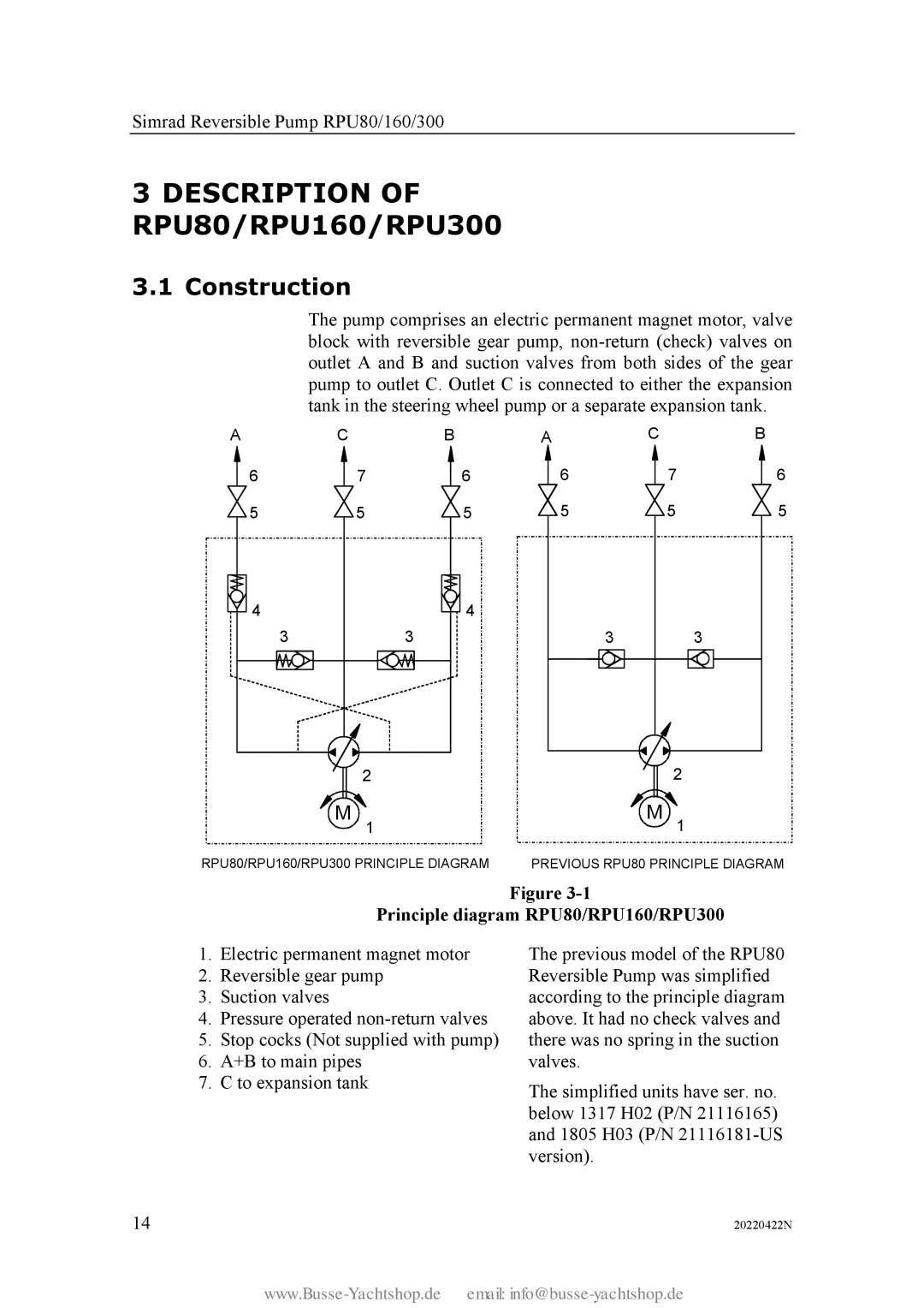
The pump comprises an electric permanent magnet motor, valve block with reversible gear pump,
A | C | B | A | C |
| B | ||||||
6 |
| 7 |
|
| 6 | 6 |
| 7 | 6 | |||
5 |
| 5 |
|
| 5 | 5 |
| 5 | 5 | |||
|
|
|
|
|
| 4 |
|
|
|
|
| |
| 4 |
|
|
|
|
|
|
|
|
|
| |
|
|
|
|
|
|
|
|
|
| |||
3 | 3 |
|
|
| 3 |
| 3 |
| ||||
|
|
|
|
|
|
|
|
|
|
|
|
|
|
|
|
|
|
|
|
|
|
|
|
|
|
| 2 | 2 |
| M 1 | M 1 |
RPU80/RPU160/RPU300 PRINCIPLE DIAGRAM | PREVIOUS RPU80 PRINCIPLE DIAGRAM | |
|
| Figure |
| Principle diagram RPU80/RPU160/RPU300 | |
1. | Electric permanent magnet motor | The previous model of the RPU80 |
2. | Reversible gear pump | Reversible Pump was simplified |
3. | Suction valves | according to the principle diagram |
4. | Pressure operated | above. It had no check valves and |
5. | Stop cocks (Not supplied with pump) | there was no spring in the suction |
6. | A+B to main pipes | valves. |
7. | C to expansion tank | The simplified units have ser. no. |
|
| |
|
| below 1317 H02 (P/N 21116165) |
|
| and 1805 H03 (P/N |
|
| version). |
14 |
| 20220422N |
