Manuals
/
Brands
/
Computer Equipment
/
Switch
/
SMC Networks
/
Computer Equipment
/
Switch
SMC Networks
SMC7824M/ESW
- page 27
1
27
104
104
Download
104 pages, 5.56 Mb
D
ESCRIPTION
OF
H
ARDWARE
1-7
Fan Tray
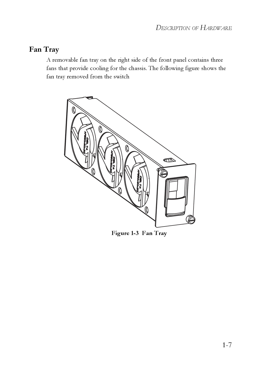
A removable fan tray on the right side of the fro
nt panel contains three
fans that provide cooling for the chassis. The following figure shows the
fan tray removed from the switch
Figure 1-3 Fan Tray
Contents
Main
TigerAccess
10/100
Fast Ethernet Switch
Installation Guide
Page
Page
Trademarks:
L
W
IMITED
v
ARRANTY
vi
vii
C
Japan VCCI Class A
FCC - Class A
Industry Canada - Class A
viii
CE Mark Declaration of Conformance for EMI and Safety (EEC)
ix
Australia AS/NZS 3548 (1995) - Class A
Safety Compliance
x
Power Cord Safety
xi
Veuillez lire fond l'information de la scurit suivante avant d'installer le Switch:
xii
Bitte unbedingt vor dem Einbauen des Switches die folgenden Sicherheitsanweisungen durchlesen:
PSE Alarm
xiii
Warnings and Cautionary Messages
War nin gs (in German)
xiv
ABLE
OF
xv
ONTENTS
1 About the TigerAccess Switch . . . . . . . . . . . . . . . . . . . 1-1
C
xvi
4 Making Network Connections . . . . . . . . . . . . . . . . . . . 4-1
APPENDICES:
Page
xix
ABLES
F
xx
IGURES
Page
T
1-2
Switch Architecture
Network Management Options
Description of Hardware
100BASE-TX and 1000BASE-T Ports
100BASE-TX Management Port
Page
Page
T
1-6
Table 1-2 Port and System Status LEDs
Page
Page
Optional Media Extender Module
Features and Benefits
Page
Page
HAPTER
2-1
2 N
P
ETWORK
LANNING
Introduction to Switching
P
2-2
Collapsed Backbone
... ... ...
E
PPLICATION
FastEthernet Switch Stack
... ...
XAMPLES
P
2-4
Remote Connections with Fiber Cable
E
2-5
Making VLAN Connections
P
2-6
Application Notes
HAPTER
3-1
3
S
THE
NSTALLING
Ethernet Cabling
Equipment Checklist
Mounting
Page
Page
Installing an Optional Module into the Switch
S
3-8
Installing an Optional SFP Transceiver
C
3-9
Grounding the Chassis
S
3-10
Connecting to a Power Source
Connecting DC Power
S
P
3-11
S
3-12
Page
S
3-14
Connecting to the Console Port
Wiring Map for Serial Cable
Connecting to the Alarm Port
S
3-16
Wiring Map for Alarm Cable
The signals include relay co ntacts for major and minor system alarms, and external alarm inputs.
P
A
3-17
Page
Page
Page
D
4-3
Network Wiring Connections
N
C
Fiber Optic SFP Devices
Page
N
C
4-6
Connectivity Rules
1000BASE-T Cable Requirements
1000 Mbps Gigabit Ethernet Cable Lengths
R
4-7
100 Mbps Fast Ethernet Cable Lengths 10 Mbps Ethernet Cable Lengths
Table 4-3 Maximum 1000BASE-LX Gigabit Ethernet Cable Length
Table 4-4 Maximum 1000BASE-ZX Gigabit Ethernet Cable Length
Cable Labeling and Connection Records
A-1
ROUBLESHOOTING
Diagnosing Switch Indicators
Table A-1 Diagnosing Switch Indicators
A-2
Table A-1 Diagnosing Switch Indicators (Continued)
P
C
Power and Cooling Problems
Installation
In-Band Access
Page
B-1
B
ABLES
Twisted-Pair Cable and Pin Assignments
B-2
10BASE-T/100BASE-TX Pin Assignments
C
A
IN
P
AND
B-4
Crossover Wiring
C
A
P
B-5
B-6
1000BASE-T Cable Requirements
Cable Testing for Existing Category 5 Cable
Adjusting Existing Category 5 Cabling to Run 1000BASE-T
Fiber Standards
Page
C-1
C S
PECIFICATIONS
Physical Characteristics
C
C-2
C-3
Switch Features
Management Features
C-4
Standards
Compliances
C-5
Extender Modules
Gigabit Extender Module (RJ-45/SFP)
Page
D-1
APPENDIX D G ERMAN I
Eine Site Auswhlen (Selecting a Site)
I
D-2
Montage (Rack Mounting Instructions)
Rack-Montage
Das Erden des Gehuses (Grounding the Chassis)
I
D-4
Anschluss an eine Stromquelle (Connecting to a Power Source)
Anschluss an Gleichstrom
Page
I
D-6
Page
Page
E-1
E O
I
RDERING
NFORMATION
Table E-1 TigerAccess 10/100 Products and Accessories
Page
G
Glossary-1
LOSSARY
Glossary-2
Glossary-3
Glossary-4
Page
Page
NDEX
Index-1
Numerics
A
B
I
L
M
N
O
R
S
T
V
W