INSTALLING THE SWITCH
5.If you have installed both a primary and redundant power conversion modules, verify that the LEDs on both modules are lit as indicated in the preceding step.
Connecting to the Console Port
The
8
8
11
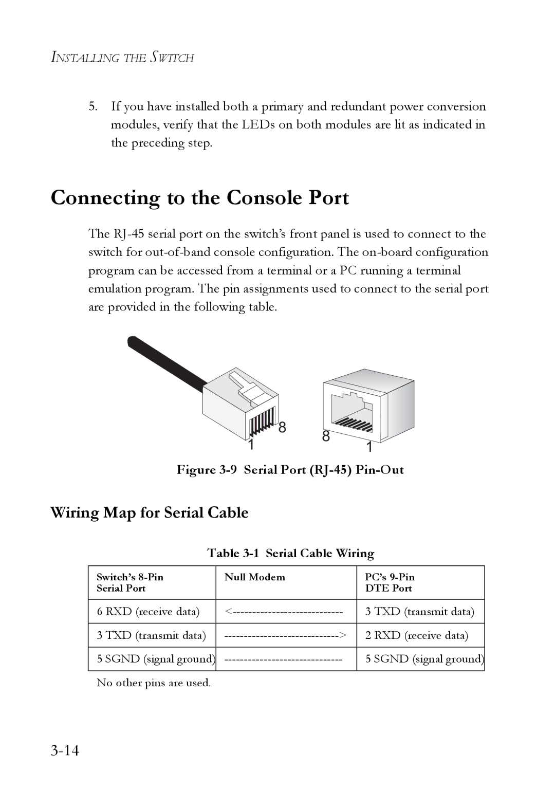
Figure 3-9 Serial Port (RJ-45) Pin-Out
Wiring Map for Serial Cable
Table 3-1 Serial Cable Wiring
Switch’s | Null Modem |
| PC’s | |
Serial Port |
|
| DTE Port | |
|
|
|
|
|
6 | RXD (receive data) | 3 TXD (transmit data) | ||
|
|
|
|
|
3 | TXD (transmit data) | > | 2 RXD (receive data) | |
|
|
|
| |
5 SGND (signal ground) | 5 SGND (signal ground) | |||
|
|
|
| |
No other pins are used. |
|
|
| |