CONNECTING TO THE ALARM PORT
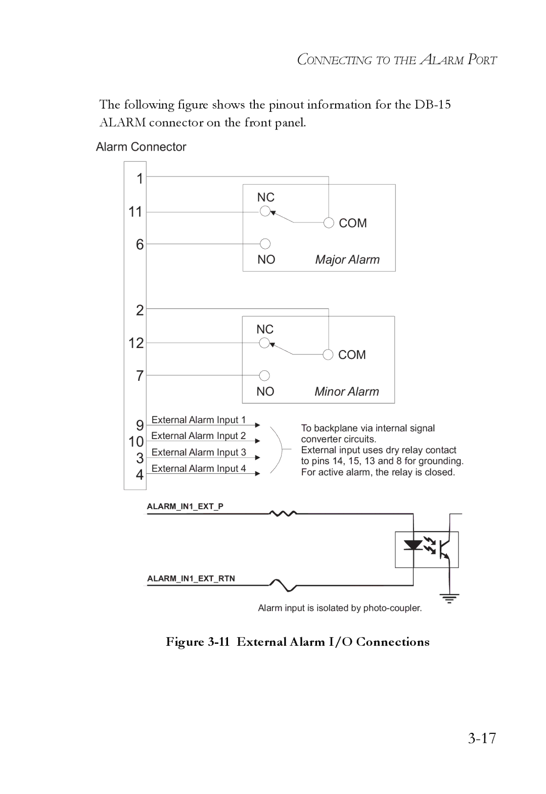
The following figure shows the pinout information for the
Alarm Connector
1
11
6
2
12
7
9
10
3
4
NC
COM
NO Major Alarm
NC
|
|
| COM | |
|
|
| Minor Alarm | |
| NO | |||
External Alarm Input 1 |
| To backplane via internal signal | ||
External Alarm Input 2 | ||||
converter circuits. | ||||
|
|
| ||
External Alarm Input 3 |
| External input uses dry relay contact | ||
to pins 14, 15, 13 and 8 for grounding. | ||||
External Alarm Input 4 | ||||
For active alarm, the relay is closed. | ||||
|
|
| ||
ALARM_IN1_EXT_P
ALARM_IN1_EXT_RTN
Alarm input is isolated by