Section 4 - ADJUSTMENT & REPAIR
WARNING
DO NOT attempt any adjustments, maintenance or service with the engine or blades running. STOP blades. STOP engine. Set brake. Remove key. Remove spark plug wire from spark plug and secure wire away from spark plug. Engine and components can be extremely hot. Avoid burns by allowing engine and components sufficient time to cool.
4.3TRACTOR DRIVE COMPONENTS 4.3.1. BRAKE ADJUSTMENT
1. | To be properly adjusted, the brake should stop |
the tractor in approximately 6 feet from top speed | |
when the clutch/brake pedal is fully depressed. | |
2. | Adjust brake when necessary as follows: |
3. | Turn engine “OFF”. Remove key. |
4. | Locate brake adjustment nut underneath the rear |
of tractor. See Figure 4.8. | |
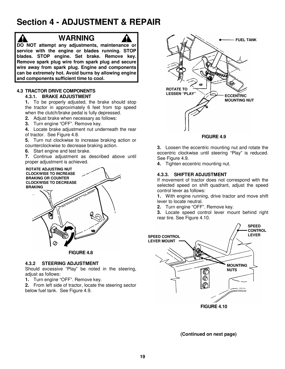
ROTATE TO LESSEN “PLAY”
FUEL TANK
ECCENTRIC MOUNTING NUT
5. | Turn nut clockwise to increase braking action or |
counterclockwise to decrease braking action. | |
6. | Start engine and test brake. |
7. | Continue adjustment as described above until |
proper adjustment is achieved. | |
ROTATE ADJUSTING NUT
CLOCKWISE TO INCREASE
BRAKING OR COUNTER
CLOCKWISE TO DECREASE
BRAKING
FIGURE 4.9
3.Loosen the eccentric mounting nut and rotate the eccentric clockwise until steering “Play” is reduced. See Figure 4.9.
4.Tighten eccentric mounting nut.
4.3.3.SHIFTER ADJUSTMENT
If movement of tractor does not correspond with the selected speed on shift quadrant, adjust the speed control lever as follows:
1.With engine running, drive tractor and move shift lever to locate neutral.
2.Turn engine “OFF”. Remove key.
3.Locate speed control lever mount behind right rear tire. See Figure 4.10.
FIGURE 4.8
SPEED CONTROL LEVER MOUNT
SPEED ![]() CONTROL LEVER
CONTROL LEVER
4.3.2STEERING ADJUSTMENT
Should excessive “Play” be noted in the steering, adjust as follows:
1.Turn engine “OFF”. Remove key.
2.From left side of tractor, locate the steering sector below fuel tank. See Figure 4.9.
MOUNTING NUTS
FIGURE 4.10
(Continued on next page)
19