Section 4 - ADJUSTMENT & REPAIR
WARNING
DO NOT attempt any adjustments, maintenance or service with the engine or blades running. STOP blades. STOP engine. Set brake. Remove key. Remove spark plug wire from spark plug and secure wire away from spark plug. Engine and components can be extremely hot. Avoid burns by allowing engine and components sufficient time to cool. Wear heavy leather gloves when handling or working around cutting blades. Blades are extremely sharp and can cause severe injury.
6.Secure stationary idler with mounting bolt.
7.Place spark plug wire onto spark plug. Set park brake. Start engine.
8.Visually inspect traction drive belt for movement. When properly adjusted, the traction drive belt should not have any movement or rotation with the engine running and park brake engaged.
9.Should movement be present, readjust traction drive belt to release belt tension as described in previous instructions.
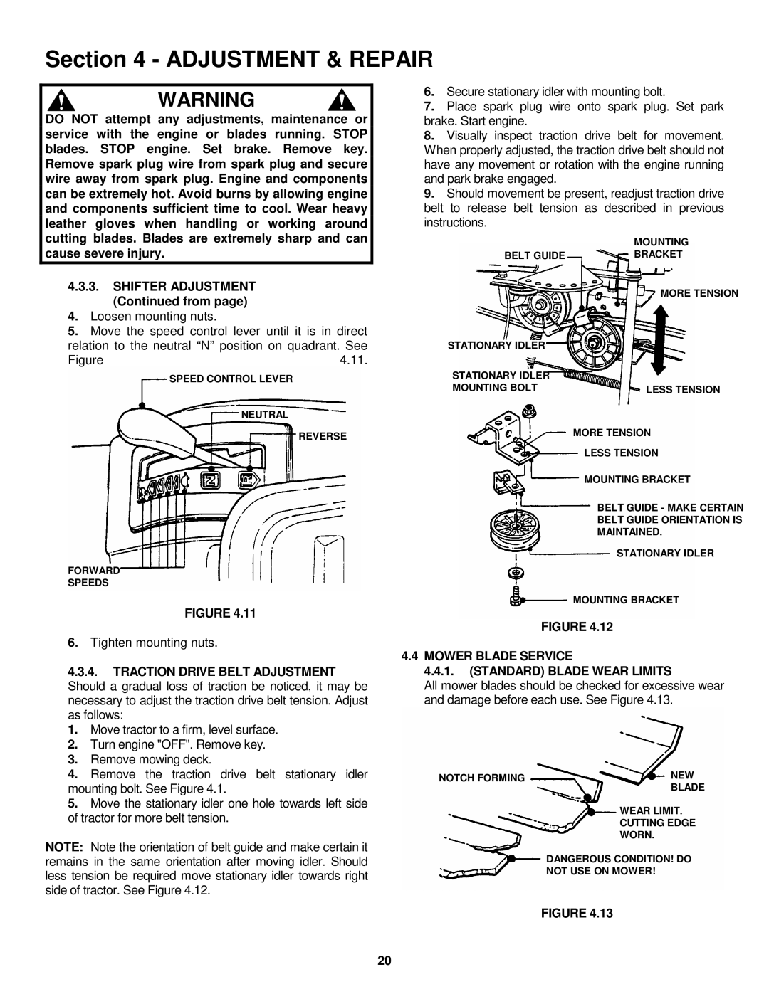
| MOUNTING |
BELT GUIDE | BRACKET |
4.3.3.SHIFTER ADJUSTMENT (Continued from page)
4.Loosen mounting nuts.
5.Move the speed control lever until it is in direct relation to the neutral “N” position on quadrant. See
Figure | 4.11. |
SPEED CONTROL LEVER
NEUTRAL
REVERSE
FORWARD
SPEEDS
STATIONARY IDLER
STATIONARY IDLER MOUNTING BOLT
MORE TENSION
LESS TENSION
MORE TENSION
LESS TENSION
MOUNTING BRACKET
BELT GUIDE - MAKE CERTAIN BELT GUIDE ORIENTATION IS MAINTAINED.
STATIONARY IDLER
FIGURE 4.11
6.Tighten mounting nuts.
4.3.4.TRACTION DRIVE BELT ADJUSTMENT Should a gradual loss of traction be noticed, it may be necessary to adjust the traction drive belt tension. Adjust as follows:
1.Move tractor to a firm, level surface.
2.Turn engine "OFF". Remove key.
3.Remove mowing deck.
4.Remove the traction drive belt stationary idler mounting bolt. See Figure 4.1.
5.Move the stationary idler one hole towards left side of tractor for more belt tension.
NOTE: Note the orientation of belt guide and make certain it remains in the same orientation after moving idler. Should less tension be required move stationary idler towards right side of tractor. See Figure 4.12.
MOUNTING BRACKET
FIGURE 4.12
4.4 MOWER BLADE SERVICE
4.4.1.(STANDARD) BLADE WEAR LIMITS
All mower blades should be checked for excessive wear and damage before each use. See Figure 4.13.
NOTCH FORMING | NEW |
| BLADE |
| WEAR LIMIT. |
| CUTTING EDGE |
| WORN. |
| DANGEROUS CONDITION! DO |
| NOT USE ON MOWER! |
|
|
FIGURE 4.13
20