INSTALLATIONS
JP7: Clear CMOS Contents
Use JP7, a
JP7
Setting
Function
|
|
|
|
|
|
| Pin | Normal |
|
|
|
|
|
|
| ||
|
|
|
|
|
|
| Short/Closed | |
|
|
|
|
|
|
| ||
|
|
|
|
|
|
|
| |
|
|
|
|
|
|
|
|
|
|
|
|
|
|
|
| Pin | Clear CMOS |
|
|
|
|
|
|
| ||
|
|
|
|
|
|
| Short/Closed | |
|
|
|
|
|
|
| ||
|
|
|
|
|
|
|
| |
|
|
|
|
|
|
|
|
|
JP8: LVDS Panel Power Select |
|
|
|
| ||||||||||
|
|
|
|
|
|
|
|
|
|
|
|
|
|
|
|
|
|
|
|
|
| JP8 |
|
| Power |
|
| ||
|
|
|
|
|
|
|
|
|
|
|
| 3.3V |
|
|
|
|
|
|
|
|
|
|
|
|
|
|
|
| |
|
|
|
|
|
|
|
|
|
|
|
| |||
|
|
|
|
|
|
|
|
|
|
|
| |||
|
|
|
|
|
|
|
|
|
|
|
|
|
|
|
|
|
|
|
|
|
|
|
|
|
|
|
|
|
|
|
|
|
|
|
|
|
|
|
|
|
| 5V |
|
|
|
|
|
|
|
|
|
|
|
|
|
|
|
| |
|
|
|
|
|
|
|
|
|
|
|
| |||
|
|
|
|
|
|
|
|
|
|
|
| |||
|
|
|
|
|
|
|
|
|
|
|
|
| ||
|
|
|
|
|
|
|
|
|
| |||||
SW1: LVDS Resolution Select |
|
|
|
| ||||||||||
|
|
|
|
|
|
|
| |||||||
|
|
| Resolution |
| ||||||||||
| OFF |
|
| ON | ON |
| 1024x768 18 bit |
| ||||||
| OFF |
|
| OFF | ON |
| 1024x768 24bit |
| ||||||
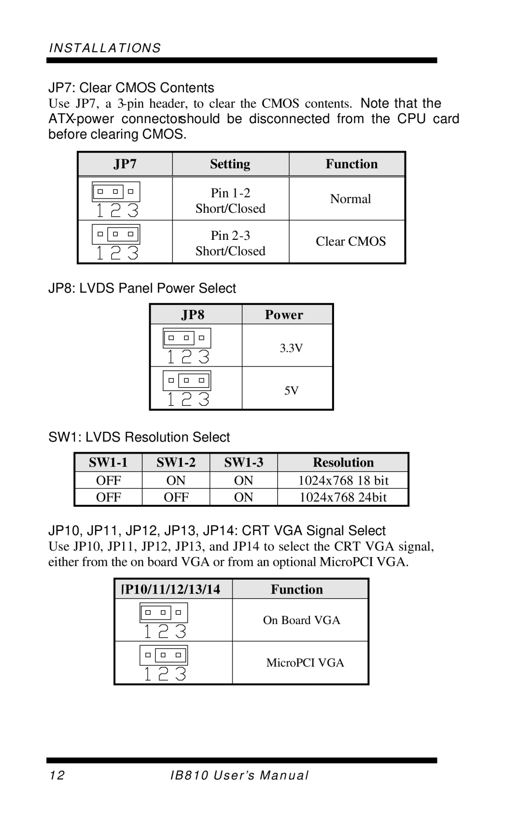
JP10, JP11, JP12, JP13, JP14: CRT VGA Signal Select
Use JP10, JP11, JP12, JP13, and JP14 to select the CRT VGA signal, either from the on board VGA or from an optional MicroPCI VGA.
JP10/11/12/13/14
Function
On Board VGA
MicroPCI VGA
12 | IB810 User’s Manual |