INSTALLATIONS
ATX Power Installation
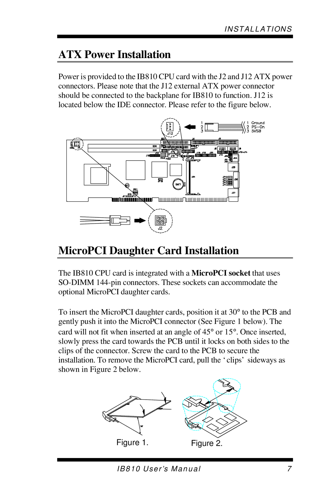
Power is provided to the IB810 CPU card with the J2 and J12 ATX power connectors. Please note that the J12 external ATX power connector should be connected to the backplane for IB810 to function. J12 is located below the IDE connector. Please refer to the figure below.
MicroPCI Daughter Card Installation
The IB810 CPU card is integrated with a MicroPCI socket that uses
To insert the MicroPCI daughter cards, position it at 30° to the PCB and gently push it into the MicroPCI connector (See Figure 1 below). The card will not fit when inserted at an angle of 45° or 15°. Once inserted, slowly press the card towards the PCB until it locks on both sides to the clips of the connector. Screw the card to the PCB to secure the installation. To remove the MicroPCI card, pull the ‘clips’ sideways as shown in Figure 2 below.
Figure 1. | Figure 2. |
IB810 User’s Manual | 7 |