AR-B1570 User’s Guide
2.5 SERIAL PORT
The ACEs (Asynchronous Communication Elements ACE1 to ACE4) are used to convert parallel data to a serial format on the transmit side and convert serial data to parallel on the receiver side. The serial format, in order of transmission and reception, is a start bit, followed by five to eight data bits, a parity bit (if programmed) and one,
1.5(in a
Provisions are also included to use this 16x clock to drive the receiver logic. Also included in the ACE a completed MODEM control capability, and a processor interrupt system that may be software tailored to the computing time required to handle the communications link.
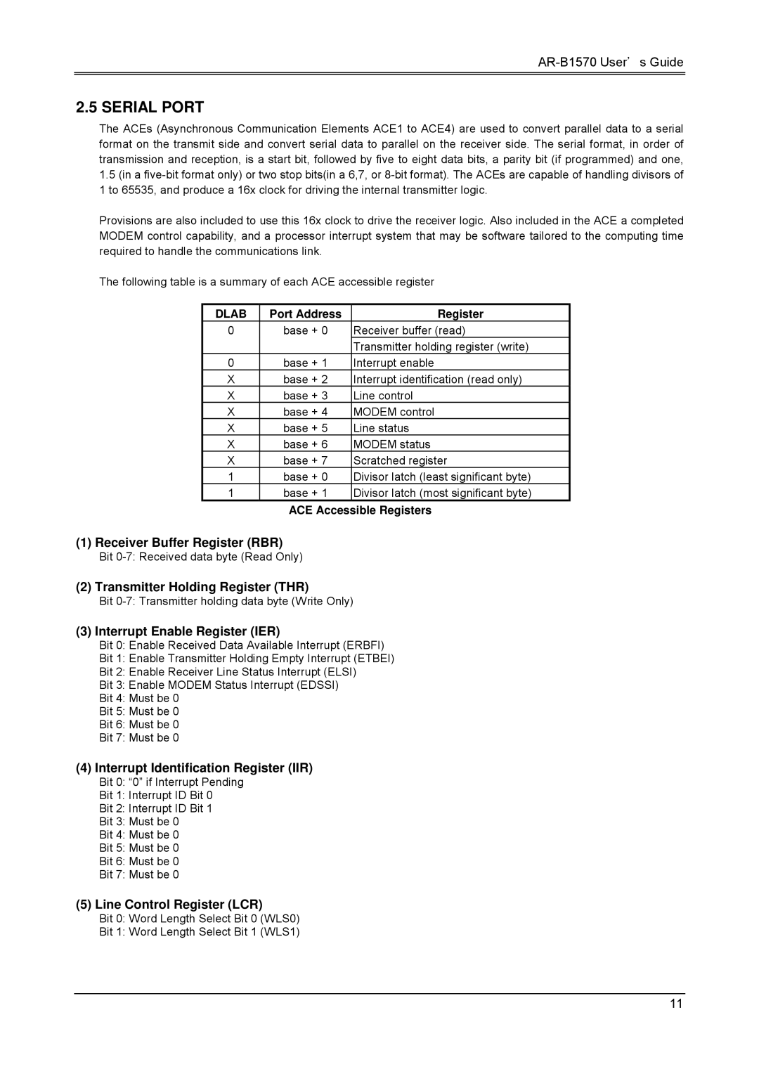
The following table is a summary of each ACE accessible register
DLAB | Port Address | Register |
0 | base + 0 | Receiver buffer (read) |
|
| Transmitter holding register (write) |
0 | base + 1 | Interrupt enable |
X | base + 2 | Interrupt identification (read only) |
X | base + 3 | Line control |
X | base + 4 | MODEM control |
X | base + 5 | Line status |
X | base + 6 | MODEM status |
X | base + 7 | Scratched register |
1 | base + 0 | Divisor latch (least significant byte) |
1 | base + 1 | Divisor latch (most significant byte) |
ACE Accessible Registers
(1) Receiver Buffer Register (RBR)
Bit
(2) Transmitter Holding Register (THR)
Bit
(3) Interrupt Enable Register (IER)
Bit 0: Enable Received Data Available Interrupt (ERBFI)
Bit 1: Enable Transmitter Holding Empty Interrupt (ETBEI)
Bit 2: Enable Receiver Line Status Interrupt (ELSI)
Bit 3: Enable MODEM Status Interrupt (EDSSI)
Bit 4: Must be 0
Bit 5: Must be 0
Bit 6: Must be 0
Bit 7: Must be 0
(4)Interrupt Identification Register (IIR)
Bit 0: “0” if Interrupt Pending
Bit 1: Interrupt ID Bit 0
Bit 2: Interrupt ID Bit 1
Bit 3: Must be 0
Bit 4: Must be 0
Bit 5: Must be 0
Bit 6: Must be 0
Bit 7: Must be 0
(5)Line Control Register (LCR)
Bit 0: Word Length Select Bit 0 (WLS0)
Bit 1: Word Length Select Bit 1 (WLS1)
11