AR-B1570 User’s Guide
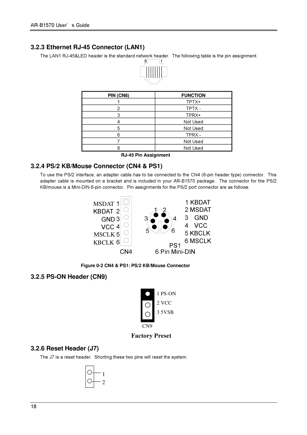
3.2.3 Ethernet RJ-45 Connector (LAN1)
The LAN1
8
1
PIN (CN8) | FUNCTION |
1 | TPTX+ |
2 | TPTX - |
3 | TPRX+ |
4 | Not Used |
5 | Not Used |
6 | TPRX - |
7 | Not Used |
8 | Not Used |
RJ-45 Pin Assignment
3.2.4 PS/2 KB/Mouse Connector (CN4 & PS1)
To use the PS/2 interface, an adapter cable has to be connected to the CN4
MSDAT 1 |
|
| 1 KBDAT | ||
KBDAT 2 |
| 1 2 | 2 MSDAT | ||
GND 3 | 3 | 4 | 3 | GND | |
VCC 4 | 5 | 6 | 4 | VCC | |
MSCLK 5 | 5 KBCLK | ||||
|
| ||||
KBCLK 6 |
| PS1 | 6 MSCLK | ||
| CN4 |
|
| ||
| 6 Pin | ||||
Figure 0-2 CN4 & PS1: PS/2 KB/Mouse Connector
3.2.5 PS-ON Header (CN9)
1
2 VCC
3 5VSB
CN9
Factory Preset
3.2.6 Reset Header (J7)
The J7 is a reset header. Shorting these two pins will reset the system.
1
2
18