|
|
| |
|
|
|
|
|
|
|
|
| Desired Baud Rate | Divisor Used to Generate 16x Clock |
|
| 300 | 384 |
|
| 600 | 192 |
|
| 1200 | 96 |
|
| 1800 | 64 |
|
| 2400 | 48 |
|
| 3600 | 32 |
|
| 4800 | 24 |
|
| 9600 | 12 |
|
| 14400 | 8 |
|
| 19200 | 6 |
|
| 28800 | 4 |
|
| 38400 | 3 |
|
| 57600 | 2 |
|
| 115200 | 1 |
|
Serial Port Divisor Latch
2.6 PARALLEL PORT
(1) Register Address
Port Address | Read/Write | Register |
base + 0 | Write | Output data |
base + 0 | Read | Input data |
base + 1 | Read | Printer status buffer |
base + 2 | Write | Printer control latch |
Registers’ Address
(2) Printer Interface Logic
The parallel port of the
(3) Data Swapper
The system microprocessor can read the contents of the printer’s Data Latch through the Data Swapper by reading the Data Swapper address.
(4) Printer Status Buffer
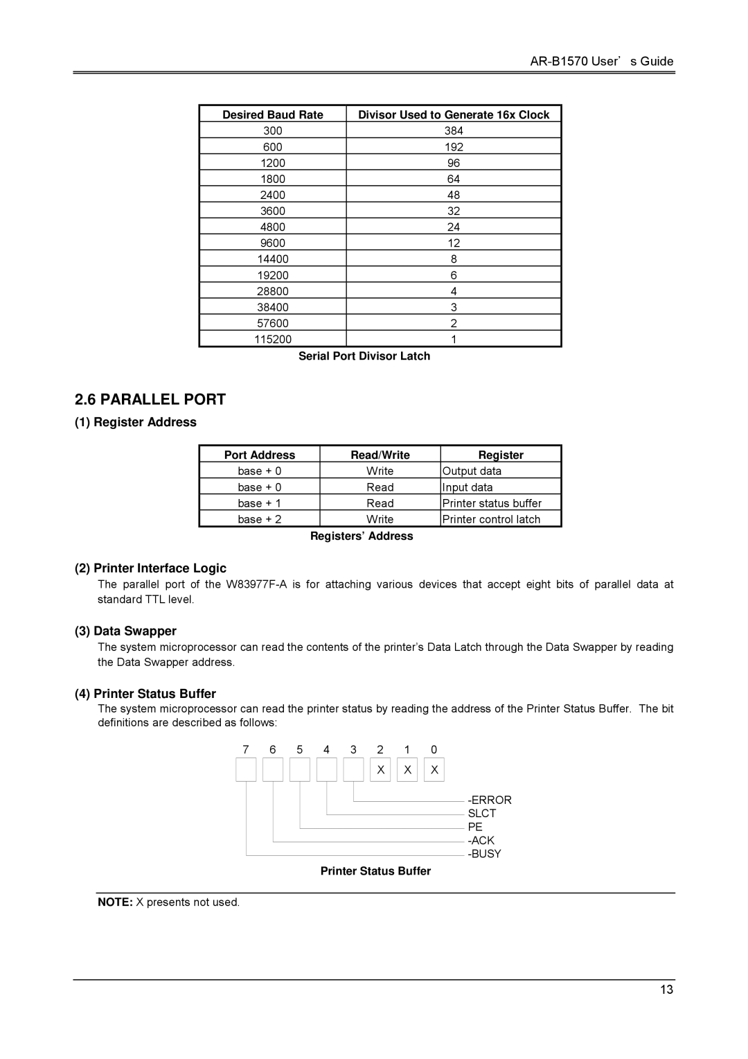
The system microprocessor can read the printer status by reading the address of the Printer Status Buffer. The bit definitions are described as follows:
7 |
| 6 | 5 | 4 | 3 | 2 |
| 1 |
| 0 | ||||
|
|
|
|
|
|
|
|
|
| X |
| X |
| X |
|
|
|
|
|
|
|
|
|
|
|
|
|
|
|
Printer Status Buffer
NOTE: X presents not used.
13
