AR-B1570 User’s Guide
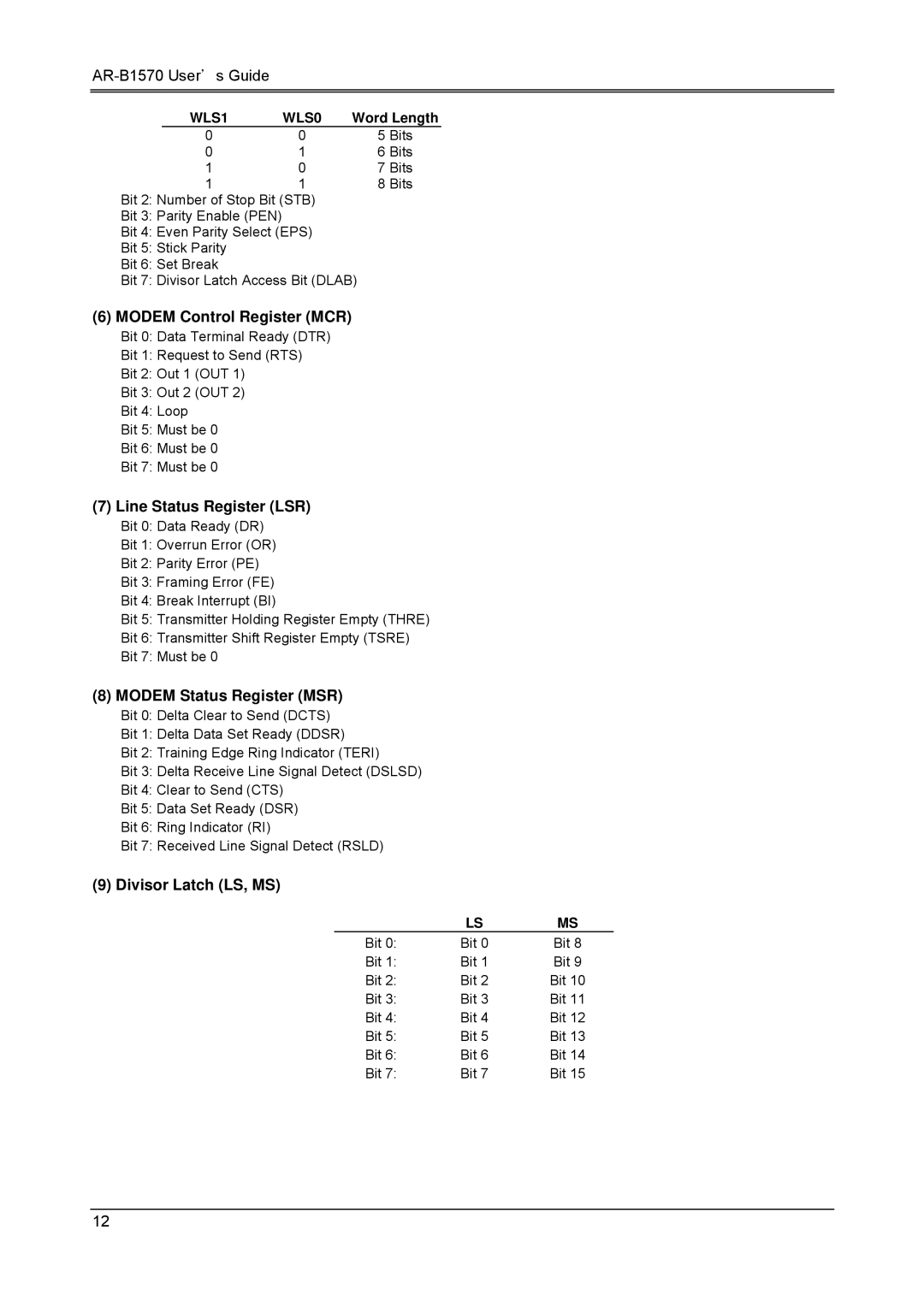
WLS1 | WLS0 | Word Length |
0 | 0 | 5 Bits |
0 | 1 | 6 Bits |
1 | 0 | 7 Bits |
1 | 1 | 8 Bits |
Bit 2: Number of Stop Bit (STB)
Bit 3: Parity Enable (PEN)
Bit 4: Even Parity Select (EPS)
Bit 5: Stick Parity
Bit 6: Set Break
Bit 7: Divisor Latch Access Bit (DLAB)
(6)MODEM Control Register (MCR)
Bit 0: Data Terminal Ready (DTR)
Bit 1: Request to Send (RTS)
Bit 2: Out 1 (OUT 1)
Bit 3: Out 2 (OUT 2)
Bit 4: Loop
Bit 5: Must be 0
Bit 6: Must be 0
Bit 7: Must be 0
(7)Line Status Register (LSR)
Bit 0: Data Ready (DR)
Bit 1: Overrun Error (OR)
Bit 2: Parity Error (PE)
Bit 3: Framing Error (FE)
Bit 4: Break Interrupt (BI)
Bit 5: Transmitter Holding Register Empty (THRE)
Bit 6: Transmitter Shift Register Empty (TSRE)
Bit 7: Must be 0
(8)MODEM Status Register (MSR)
Bit 0: Delta Clear to Send (DCTS)
Bit 1: Delta Data Set Ready (DDSR)
Bit 2: Training Edge Ring Indicator (TERI)
Bit 3: Delta Receive Line Signal Detect (DSLSD)
Bit 4: Clear to Send (CTS)
Bit 5: Data Set Ready (DSR)
Bit 6: Ring Indicator (RI)
Bit 7: Received Line Signal Detect (RSLD)
(9)Divisor Latch (LS, MS)
| LS | MS |
Bit 0: | Bit 0 | Bit 8 |
Bit 1: | Bit 1 | Bit 9 |
Bit 2: | Bit 2 | Bit 10 |
Bit 3: | Bit 3 | Bit 11 |
Bit 4: | Bit 4 | Bit 12 |
Bit 5: | Bit 5 | Bit 13 |
Bit 6: | Bit 6 | Bit 14 |
Bit 7: | Bit 7 | Bit 15 |
12