Getting Started
Names and Functions of Parts
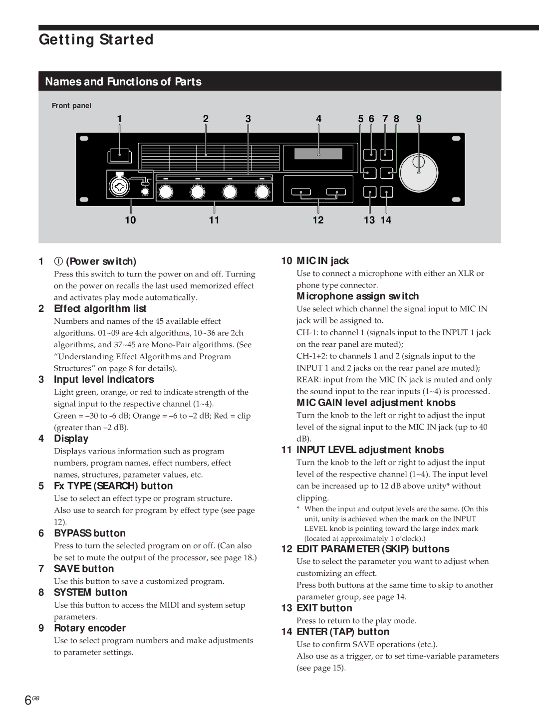
Front panel
1 | 2 | 3 |
1011
1 U (Power switch)
Press this switch to turn the power on and off. Turning on the power on recalls the last used memorized effect and activates play mode automatically.
2 Effect algorithm list
Numbers and names of the 45 available effect algorithms. 01~09 are 4ch algorithms, 10~36 are 2ch algorithms, and 37~45 are
3 Input level indicators
Light green, orange, or red to indicate strength of the signal input to the respective channel (1~4).
Green =
4 Display
Displays various information such as program numbers, program names, effect numbers, effect names, structures, parameter values, etc.
5 Fx TYPE (SEARCH) button
Use to select an effect type or program structure.
Also use to search for program by effect type (see page 12).
6 BYPASS button
Press to turn the selected program on or off. (Can also be set to mute the output of the processor, see page 18.)
7 SAVE button
Use this button to save a customized program.
8 SYSTEM button
Use this button to access the MIDI and system setup parameters.
9 Rotary encoder
Use to select program numbers and make adjustments to parameter settings.
4 | 5 6 | 7 | 8 | 9 |
|
|
|
|
|
|
|
|
|
|
12 | 13 14 |
10 MIC IN jack
Use to connect a microphone with either an XLR or phone type connector.
Microphone assign switch
Use select which channel the signal input to MIC IN jack will be assigned to.
MIC GAIN level adjustment knobs
Turn the knob to the left or right to adjust the input level of the signal input to the MIC IN jack (up to 40 dB).
11 INPUT LEVEL adjustment knobs
Turn the knob to the left or right to adjust the input level of the respective channel (1~4). The input level can be increased up to 12 dB above unity* without clipping.
*When the input and output levels are the same. (On this unit, unity is achieved when the mark on the INPUT LEVEL knob is pointing toward the large index mark (located at approximately 1 o’clock).)
12 EDIT PARAMETER (SKIP) buttons
Use to select the parameter you want to adjust when customizing an effect.
Press both buttons at the same time to skip to another parameter group, see page 14.
13 EXIT button
Press to return to the play mode.
14 ENTER (TAP) button
Use to confirm SAVE operations (etc.).
Also use as a trigger, or to set
6GB