Color Rear Video Projector
Microfilm
Video 3
Specifications
Video 1 Video 2 Input
Monitor OUT
Summary of Self-Diagnosis Function
Blinking count display of TIMER/STAVDBY indicator
Self Diagnosis Function
Diagnosis Items and Prediction of Malfunction Location
Self-diagnosis screen displays
Self-Diagnosis Screen Display
OVP Detect
Self-diagnosis block diagram
Self-diagnosis function operation
OCP Detect
Disassembly
Table of Contents
Circuit Adjustments
SET-UP Adjustments
Section General
Function
Carrying Your Projection TV Installing the Projection TV
Connector Types
Making Connections
Connecting a cable TV system/ antenna to a VCR
Connecting a VCR and projection TV to a cable box
Connecting a camcorder
Connecting two VCRs for tape editing
Connecting a DVD Player Upper illustration
Connecting an audio system Upper illustration
Using the Remote Control
Setting Up the Projection TV Automatically
Inserting the batteries
Adjusting the Convergence Automatically Flash Focus
To perform Auto SET UP again
Watching the TV
Using the Yellow Labeled Buttons for PIP Operations
Watching Two Programs at One Time PIP
Learning Menu Selection
To exit from the menus at any t i m e
To restore the factory settings
Using the Video Menu
Using the Audio Menu
To select the Video menu
Using the Reloj Menu
To select the Reloj menu
Ch Using the Ajustes de canal M e n u
To select the Ajustes de canal ch menu
Using Canal favorito
Setting and Selecting Canal favorito
Setting Canal favorito manually
Changing Canal favorito choices
Using the Ajustes Menu
To select the Ajustes menu
Setting the Manufacturers Code
To operate the projection TV
Manufacturer code numbers cable box
To operate the cable box
Picture turns off
UHF when using an antenna
Using a cable box
Double images or ghosts
Section Disassembly
Rear Board Removal Service Position
Beznet Assy Removal
HA Board and HB Board Removal
KP-43T70C
Mirror Cover Removal
Removal
Picture Tube Removal
Focus Lens Adjustment
Section SET-UP Adjustments
Screen Voltage Adjustment Rough Alignment
Screen G2 Adjustment
Pole Magnet Adjustment
Deflection Yoke Tilt Adjustment
Pole Magnet Adjustment GREEN,RED
Defocus Adjustment Blue
Method of Settingthe Service Adjustment Mode
Electrical Adjustment by Remote Commander
Adjust Buttons and Indicator
Service Mode Adjustment
Vpnv
Adjustment Data Standard Number Range
Vpnt
Vpns
Adjustment Data Standard Number
Pjed
3DCM
Tone
DSP
DAC
CCD
Registration Adjustment
Setup for Adjustment
SUB Deflection Adjustment Item
Green Center
Green Registration Adjustment
Fine Adjustment
Green Skew
RED Registration Adjustment
Blue Registration Adjustment
Final Check
Auto Registration Error Code List Error Code List
Error Code Screen Display Sensor Position
Error Code Display in Regi Service Mode
Section Safety Related Adjustments
+B OVP Confirmation
Section Circuit Adjustments
TV Input SUB Contrast Adjustment VPNT-SCON
P & P SUB Contrast Adjustment SC-SYDR
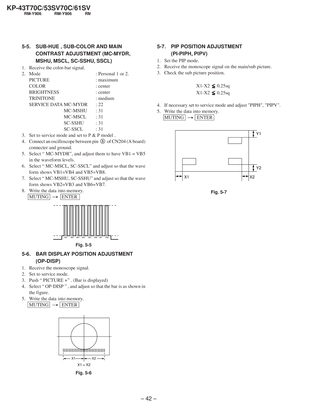
PIP Position Adjustment PI-PIPH, Pipv
BAR Display Position Adjustment OP-DISP
X1 =
Section Diagrams
Block Diagram
TUNER, VIDEO, Audio IN/OUT
4 Video
Buff
Reset
Peak Hold
IC805 PJED-CPU
To a
CN204
POWERH/V Outsupply
Frame Schematic Diagram
Part replaced Adjustment
Circuit Boards Location
3 Board Waveforms
3 Board IC406 TDA7265 3 Board IC1011 CXA2079Q
3 Board IC807, 815, 816
BV DAC
? a 2/3 board
3 Board IC1903 BU4053BCF-T2
Board
3 Board IC1902 CXA2019AQ-T4
3 Board IC1904 CXA1315M-T4
Board Waveforms
Board IC654 DM-58
Board IC651 μPC393C
CG CR CB board
CB Board Waveform
CG Board
CR Board Waveform
CB Board
HA Board HC Board
Function Keys
HB Board
FA Board
6 0 H z
Semiconductors
SLR-325VCT31
2SK2663 2SC3271F-N
1SS133-T-77 D3S6M-F ERA22-08 ERC04-06SE ERC06-15S
UDZS-TE17-8.2B
Section Exploded Views
Cover KP-43T70C
Cover Except KP-43T70C
REF. NO. Part NO. Description
Chassis KP-43T70C
103 !1-223-925-11 Resistor Assy Higvoltage Focus Pack
153 152 151 159 158 154 156 155 160 161 162 163 165
Chassis Except KP-43T70C
218 217 220
Picture Tube
Section Electrical Parts List
RM-Y906 RM-Y906
REF. no
Mylar
103
104
PLUG, Connector 10P
Short Connector
PLUG, Connector 4P
CONNECTOR, Board to Board 11P
Ferrite
Diode DTZ10B
Ferritebead
RES,CHIP
FILTER, LOW Pass Coil
REF. no Description Remark
Jack BLOCK, PIN Monitor OUT
Inductor
108
RM-Y906
Metal Chip
Metal Oxide
Carbon
112
113
Tuner
FSS Tuner BTF-WA411
TUNER, FSS BTF-FA401
SCREW+PSW
Crystal
SHIELD, Transformer
Ceramic 2KV
TAB Contact
PIN, Connector 2P
PLUG, Connector 3P
1KV
Diode D4SBS4-F
Diode GP08D
Diode EL1Z
Diode D1NL20U
Carbon Photo Coupler
Neon Lamp
LAMP, Neon
Photo Coupler ON3171-R
119
120
CR BOARD, Complete
Relay
Test PIN
Ferrite Neon Lamp
CG BOARD, Complete
L731 Inductor
PLUG, Connector 9P
GAP, Spark Connector Test PIN
PLUG, Connector 5P
PLUG, Connector 3P Coil Diode
Carbon Switch
HA BOARD, Complete Connector
Switch S1201 1-572-198-11 SWITCH, Keyboard Flash Focus
HB BOARD, Complete Capacitor
Remote Commander RM-Y906
CABLE, P-P Remote Commander
CABLE, P-P CORD, Power with Connector
COVER, Battery for RM-Y906
Sony Corporation
965-408-01