KP-43T70C/53SV70C/61SV70C
RM-Y906 RM-Y906 RM-Y906
SELF DIAGNOSIS FUNCTION
1.Summary of Self-Diagnosis Function
•This device includes a
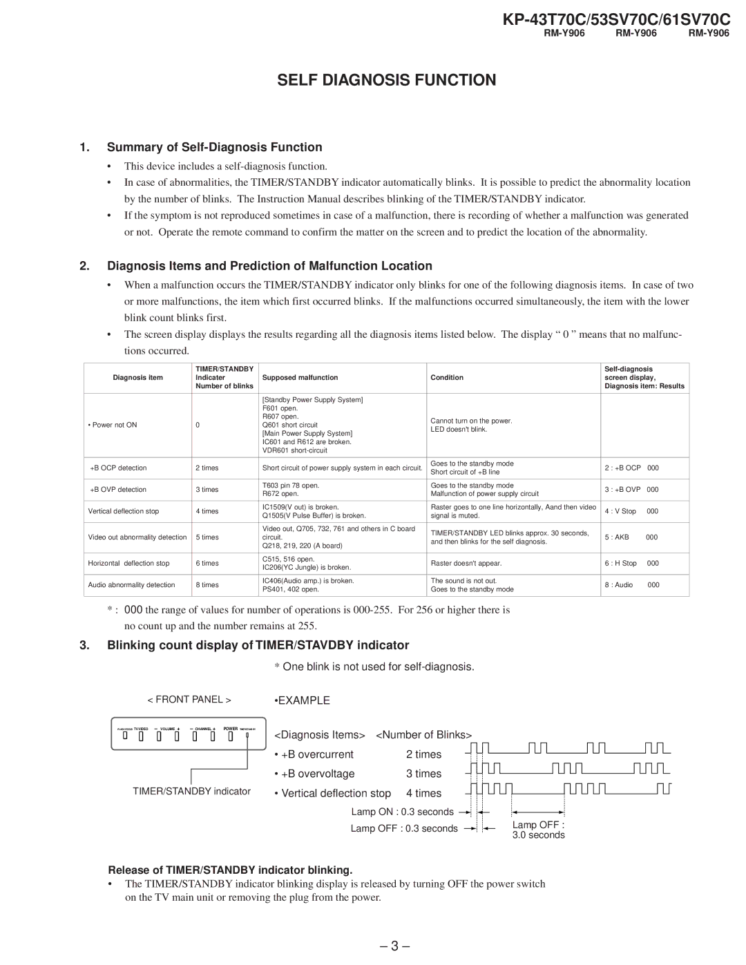
•In case of abnormalities, the TIMER/STANDBY indicator automatically blinks. It is possible to predict the abnormality location by the number of blinks. The Instruction Manual describes blinking of the TIMER/STANDBY indicator.
•If the symptom is not reproduced sometimes in case of a malfunction, there is recording of whether a malfunction was generated or not. Operate the remote command to confirm the matter on the screen and to predict the location of the abnormality.
2.Diagnosis Items and Prediction of Malfunction Location
•When a malfunction occurs the TIMER/STANDBY indicator only blinks for one of the following diagnosis items. In case of two or more malfunctions, the item which first occurred blinks. If the malfunctions occurred simultaneously, the item with the lower blink count blinks first.
•The screen display displays the results regarding all the diagnosis items listed below. The display “ 0 ” means that no malfu nc- tions occurred.
| TIMER/STANDBY |
|
| |||
Diagnosis item | Indicater | Supposed malfunction | Condition | screen display, | ||
| Number of blinks |
|
| Diagnosis item: Results | ||
|
|
|
|
|
| |
|
| [Standby Power Supply System] |
|
|
| |
|
| F601 open. |
|
|
| |
|
| R607 open. | Cannot turn on the power. |
|
| |
• Power not ON | 0 | Q601 short circuit |
|
| ||
LED doesn't blink. |
|
| ||||
|
| [Main Power Supply System] |
|
| ||
|
|
|
|
| ||
|
| IC601 and R612 are broken. |
|
|
| |
|
| VDR601 |
|
|
| |
|
|
|
|
|
| |
+B OCP detection | 2 times | Short circuit of power supply system in each circuit. | Goes to the standby mode | 2 : +B OCP | 000 | |
Short circuit of +B line | ||||||
|
|
|
|
| ||
|
|
|
|
|
| |
+B OVP detection | 3 times | T603 pin 78 open. | Goes to the standby mode | 3 : +B OVP | 000 | |
R672 open. | Malfunction of power supply circuit | |||||
|
|
|
| |||
|
|
|
|
|
| |
Vertical deflection stop | 4 times | IC1509(V out) is broken. | Raster goes to one line horizontally, Aand then video | 4 : V Stop | 000 | |
Q1505(V Pulse Buffer) is broken. | signal is muted. | |||||
|
|
|
| |||
|
|
|
|
|
| |
|
| Video out, Q705, 732, 761 and others in C board | TIMER/STANDBY LED blinks approx. 30 seconds, |
|
| |
Video out abnormality detection | 5 times | circuit. | 5 : AKB | 000 | ||
and then blinks for the self diagnosis. | ||||||
|
| Q218, 219, 220 (A board) |
|
| ||
|
|
|
|
| ||
|
|
|
|
|
| |
Horizontal deflection stop | 6 times | C515, 516 open. | Raster doesn't appear. | 6 : H Stop | 000 | |
IC206(YC Jungle) is broken. | ||||||
|
|
|
|
| ||
|
|
|
|
|
| |
Audio abnormality detection | 8 times | IC406(Audio amp.) is broken. | The sound is not out. | 8 : Audio | 000 | |
PS401, 402 open. | Goes to the standby mode | |||||
|
|
|
| |||
|
|
|
|
|
| |
*: 000 the range of values for number of operations is
3. Blinking count display of TIMER/STAVDBY indicator
< FRONT PANEL >
FLASH FOCUS TV/VIDEO – VOLUME + | – CHANNEL + POWER TIMER/STAND BY |
TIMER/STANDBY indicator
*One blink is not used for
•EXAMPLE
<Diagnosis Items> <Number of Blinks>
• +B overcurrent | 2 times |
• +B overvoltage | 3 times |
• Vertical deflection stop | 4 times |
Lamp ON : 0.3 seconds
Lamp OFF : 0.3 seconds
Lamp OFF : 3.0 seconds
Release of TIMER/STANDBY indicator blinking.
•The TIMER/STANDBY indicator blinking display is released by turning OFF the power switch on the TV main unit or removing the plug from the power.
– 3 –
