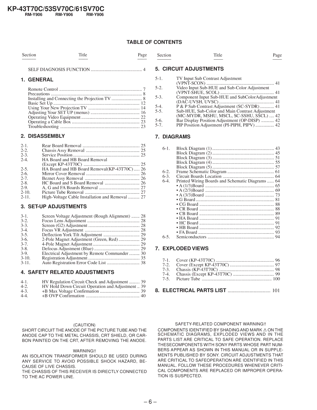
KP-43T70C/53SV70C/61SV70C
RM-Y906 RM-Y906 RM-Y906
TABLE OF CONTENTS
Section | Title | Page |
| ||
SELF DIAGNOSIS FUNCTION | 4 | |
1. GENERAL |
|
|
Remote Control | 7 | |
Precautions | 8 | |
Installing and Connecting the Projection TV | 8 | |
Basic Set Up | 12 | |
Using Your New Projection TV | 14 | |
Adjusting Your SET UP (menus) | 16 | |
Operating Video Equipment | 22 | |
Operating a Cable Box | 23 | |
Troubleshooting | 23 | |
Section | Title | Page |
5. CIRCUIT ADJUSTMENTS
TV Input Sub Contrast Adjustment |
| |
| 41 | |
Video Input |
| |
| 41 | |
Component Input | ||
| 41 | |
P & P Sub Contrast Adjustment | 41 | |
| ||
| 42 | |
Bar Display Position Adjustment | 42 | |
PIP Position Adjustment | 42 | |
2. DISASSEMBLY
Rear Board Removal | 25 | |
Chassis Assy Removal | 25 | |
Service Position | 25 | |
HA Board and HB Board Removal |
| |
| (Except | 25 |
HA Board and HB Board | 26 | |
Mirror Cover Removal | 26 | |
Beznet Assy Removal | 26 | |
HC Board and S Board Removal | 26 | |
A, G and FA Boards Removal | 27 | |
Picture Tube Removal | 27 | |
27 | ||
3. |
| |
Screen Voltage Adjustment (Rough Alignment) | 28 | |
Focus Lens Adjustment | 28 | |
Screen (G2) Adjustment | 28 | |
Focus VR Adjustment | 28 | |
Deflection York Tilt Adjustment | 29 | |
29 | ||
29 | ||
Defocus Adjustment (Blue) | 29 | |
Electrical Adjustment by Remote Commander | 30 | |
Registration Adjustment | 35 | |
Auto Registration Error Code List | 38 | |
4. SAFETY RELATED ADJUSTMENTS |
| |
HV Regulation Circuit Check and Adjustment | 39 | |
HV Hold Down Circuit Operation and Adjustment .. | 39 | |
+B Max Voltage Confirmation | 39 | |
+B OVP Confirmation | 40 | |
7. DIAGRAMS
Block Diagram (1) | 43 | |
| Block Diagram (2) | 45 |
| Block Diagram (3) | 51 |
| Block Diagram (4) | 55 |
| Block Diagram (5) | 57 |
Frame Schematic Diagram | 61 | |
Circuit Boards Location | 64 | |
64 | ||
| • A (1/3)Board | 65 |
| • A (2/3)Board | 69 |
| • A (3/3)Board | 73 |
| • G Board | 81 |
| • CG Board | 88 |
| • CR Board | 88 |
| • CB Board | 89 |
| • HA Board | 91 |
| • HC Board | 91 |
| • HB Board | 92 |
| • FA Board | 93 |
Semiconductors | 94 | |
7. EXPLODED VIEWS |
| |
Cover | 96 | |
Cover (Except | 97 | |
Chassis | 98 | |
Chassis (Except | 99 | |
Picture Tube | 100 | |
8. ELECTRICAL PARTS LIST | 101 | |
(CAUTION)
SHORT CIRCUIT THE ANODE OF THE PICTURE TUBE AND THE ANODE CAP TO THE METAL CHASSIS, CRT SHIELD, OR CAR- BON PAINTED ON THE CRT, AFTER REMOVING THE ANODE.
WARNING!!
AN ISOLATION TRANSFORMER SHOULD BE USED DURING ANY SERVICE TO AVOID POSSIBLE SHOCK HAZARD, BE- CAUSE OF LIVE CHASSIS.
THE CHASSIS OF THIS RECElVER IS DIRECTLY CONNECTED TO THE AC POWER LINE.
COMPONENTS IDENTIFIED BY SHADING AND MARK !ON THE SCHEMATIC DIAGRAMS, EXPLODED VIEWS AND IN THE
PARTS LIST ARE CRITICAL TO SAFE OPERATION. REPLACE THESECOMPONENTS WITH SONY PARTS WHOSE PART NUM- BERS APPEAR AS SHOWN IN THIS MANUAL OR IN SUPPLE- MENTS PUBLISHED BY SONY. CIRCUIT ADJUSTMENTS THAT ARE CRITICAL TO SAFEOPERATION ARE IDENTIFIED IN THIS MANUAL. FOLLOW THESE PROCEDURES WHENEVER CRITI- CAL COMPONENTS ARE REPLACED OR IMPROPER OPERA- TION IS SUSPECTED.
– 6 –
