5-7-4. Auto Check
This test mode performs CREC and CPLAY automatically for mainly checking the characteristics of the optical
Procedure:
1.Click the [ENTER/YES]. If “LDPWR ![]()
![]()
![]()
![]()
![]() ” is displayed, it means that the laser power check has not been performed. In this case, perform the laser power check and Iop compare, and then repeat from step 1.
” is displayed, it means that the laser power check has not been performed. In this case, perform the laser power check and Iop compare, and then repeat from step 1.
2.If a disc is in the mechanical deck, it will be ejected forcibly. “DISC IN” will be displayed in this case. Load a test disc (MDW-
3.If a disk is loaded at step 2, the check will start automatically.
4.When “XX CHECK” is displayed, the item corresponding to XX will be performed.
When “06 CHECK” completes, the disc loaded at step 2 will be ejected. “DISC IN” will be displayed. Load the check disc (MD)
5.When the disc is loaded, the check will automatically be resumed from “07 CHECK”.
6.After completing to test item “12 check”, check OK or NG will be displayed. If all items are OK, “CHECK ALL OK” will be displayed. If any item is NG, it will be displayed as “NG:xxxx”.
When “CHECK ALL OK” is displayed, it means that the optical
When displayed as “NG:xxxx”, it means that the optical
5-7-5. Other Checks
All the following checks are performed by the Auto Check mode. They therefore need not be performed in normal operation.
MDS-NT1
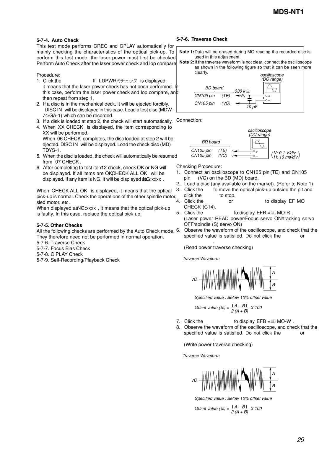
5-7-6. Traverse Check
Note 1: Data will be erased during MO reading if a recorded disc is used in this adjustment.
Note 2: If the traverse waveform is not clear, connect the oscilloscope as shown in the following figure so that it can be seen more clearly.
BD board
![]() 330 k Ω
330 k Ω
CN105 pin 4 (TE)
CN105 pin 6 (VC) ![]()
![]() 10 pF
10 pF
Connection:
|
| oscilloscope |
| |
|
| (DC range) |
| |
BD board |
|
| ||
CN105 pin 4 | (TE) | + | V: 0.1 V/div | |
CN105 pin 6 | (VC) | |||
– | H: 10 ms/div | |||
|
|
| ||
Checking Procedure:
1.Connect an oscilloscope to CN105 pin 4 (TE) and CN105 pin 6 (VC) on the BD (MD) board.
2.Load a disc (any available on the market). (Refer to Note 1)
3.Click the [FF] to move the optical
4.Click the [JOG UP] or [JOG DOWN] to display “EF MO CHECK”(C14).
5.Click the [ENTER/YES] to display “EFB = ![]()
![]()
6.Observe the waveform of the oscilloscope, and check that the specified value is satisfied. Do not click the [JOG UP] or
[JOG DOWN].
(Read power traverse checking)
Traverse Waveform
A
VC
B
Specified value : Below 10% offset value
Offset value (%) = I A – B I X 100 2 (A + B)
7.Click the [ENTER/YES] to display “EFB = ![]()
![]()
8.Observe the waveform of the oscilloscope, and check that the specified value is satisfied. Do not click the [JOG UP] or
[JOG DOWN].
(Write power traverse checking)
Traverse Waveform
A
VC
B
Specified value : Below 10% offset value
Offset value (%) = I A – B I X 100 2 (A + B)
29