For Machines Mfg. Since 8/09 | O P E R A T I O N | Model SB1027 |
Tools Needed | Qty |
Dial Test Indicator |
|
(with at least 0.0005" resolution) | ................... 1 |
Indicator Holder |
|
(mounted on the quill/spindle) | 1 |
Precision Parallel Block |
|
(at least 9" in length) | 1 |
Note: A
To tram the spindle to the table:
1.DISCONNECT MILL FROM POWER!
2.Prepare the mill by performing the following tasks:
•Stone the table to remove all nicks and burrs, then clean off all debris. Verify the table is clean by running your hand over the top of it.
•Position the table for the milling operation you intend to perform after the
•Tighten any table, knee, quill, or ram locks that should be tight during the intended milling operation.
3.Place the parallel block underneath the spindle.
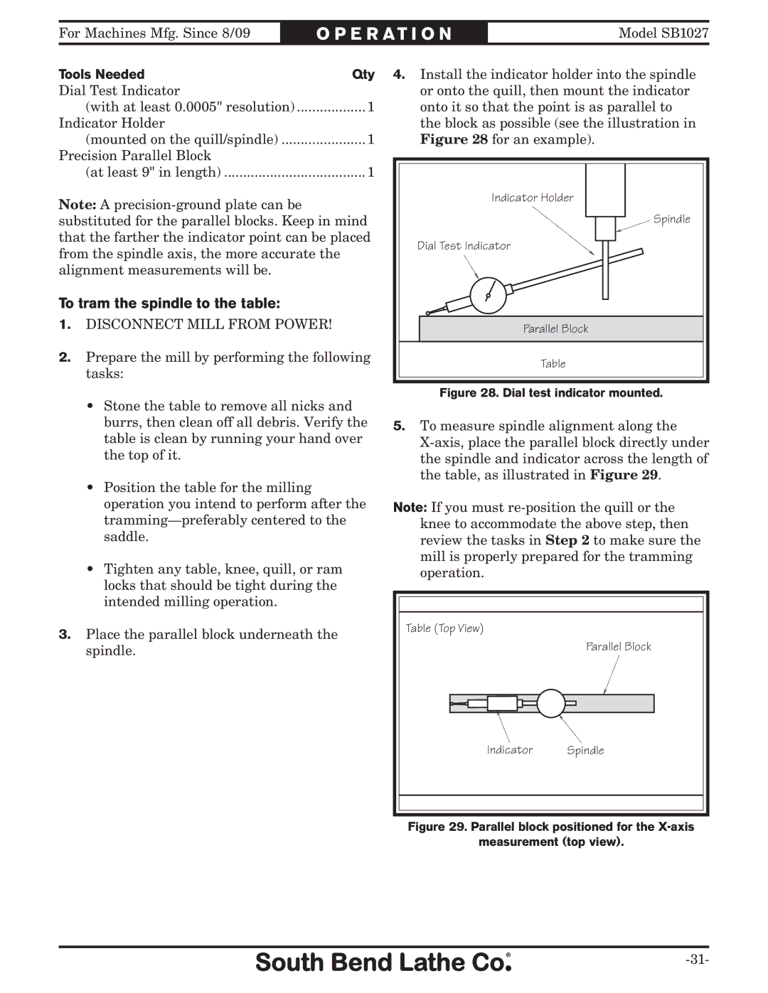
4.Install the indicator holder into the spindle or onto the quill, then mount the indicator onto it so that the point is as parallel to the block as possible (see the illustration in Figure 28 for an example).
Indicator Holder |
Spindle |
Dial Test Indicator |
Parallel Block |
Table |
Figure 28. Dial test indicator mounted.
5.To measure spindle alignment along the
Note: If you must
Table (Top View)
Parallel Block
Indicator Spindle