SEZ SERIES COUNTERTOP STEAMERS | TROUBLESHOOTING |
Figure 14
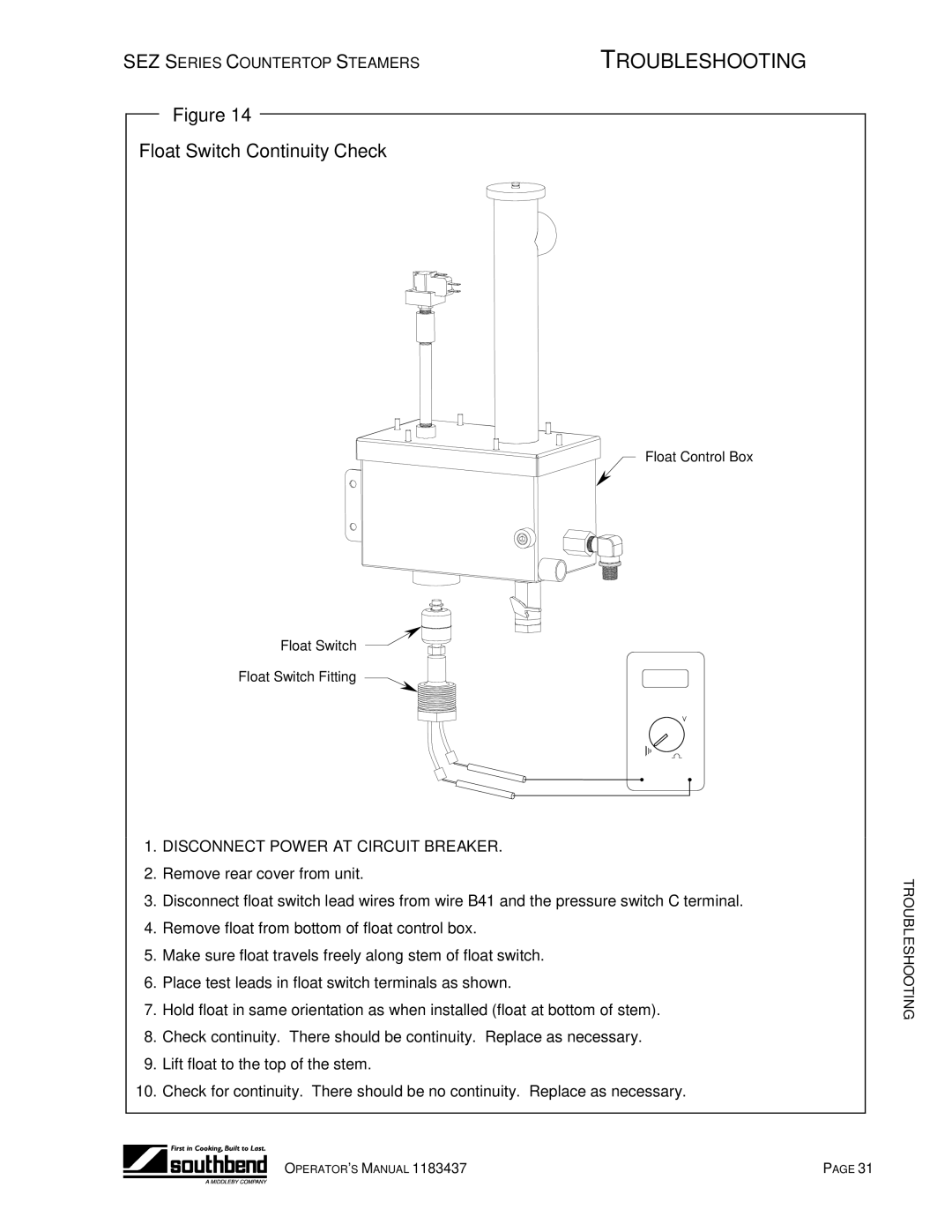
Float Switch Continuity Check
Float Control Box
Float Switch
Float Switch Fitting
1.DISCONNECT POWER AT CIRCUIT BREAKER.
2.Remove rear cover from unit.
3.Disconnect float switch lead wires from wire B41 and the pressure switch C terminal.
4.Remove float from bottom of float control box.
5.Make sure float travels freely along stem of float switch.
6.Place test leads in float switch terminals as shown.
7.Hold float in same orientation as when installed (float at bottom of stem).
8.Check continuity. There should be continuity. Replace as necessary.
9.Lift float to the top of the stem.
10.Check for continuity. There should be no continuity. Replace as necessary.
TROUBLESHOOTING
OPERATOR’S MANUAL 1183437 | PAGE 31 |