2-2. Setting Daylight Saving Time
To enable Daylight Saving feature/NTP synchronization, take the following steps.
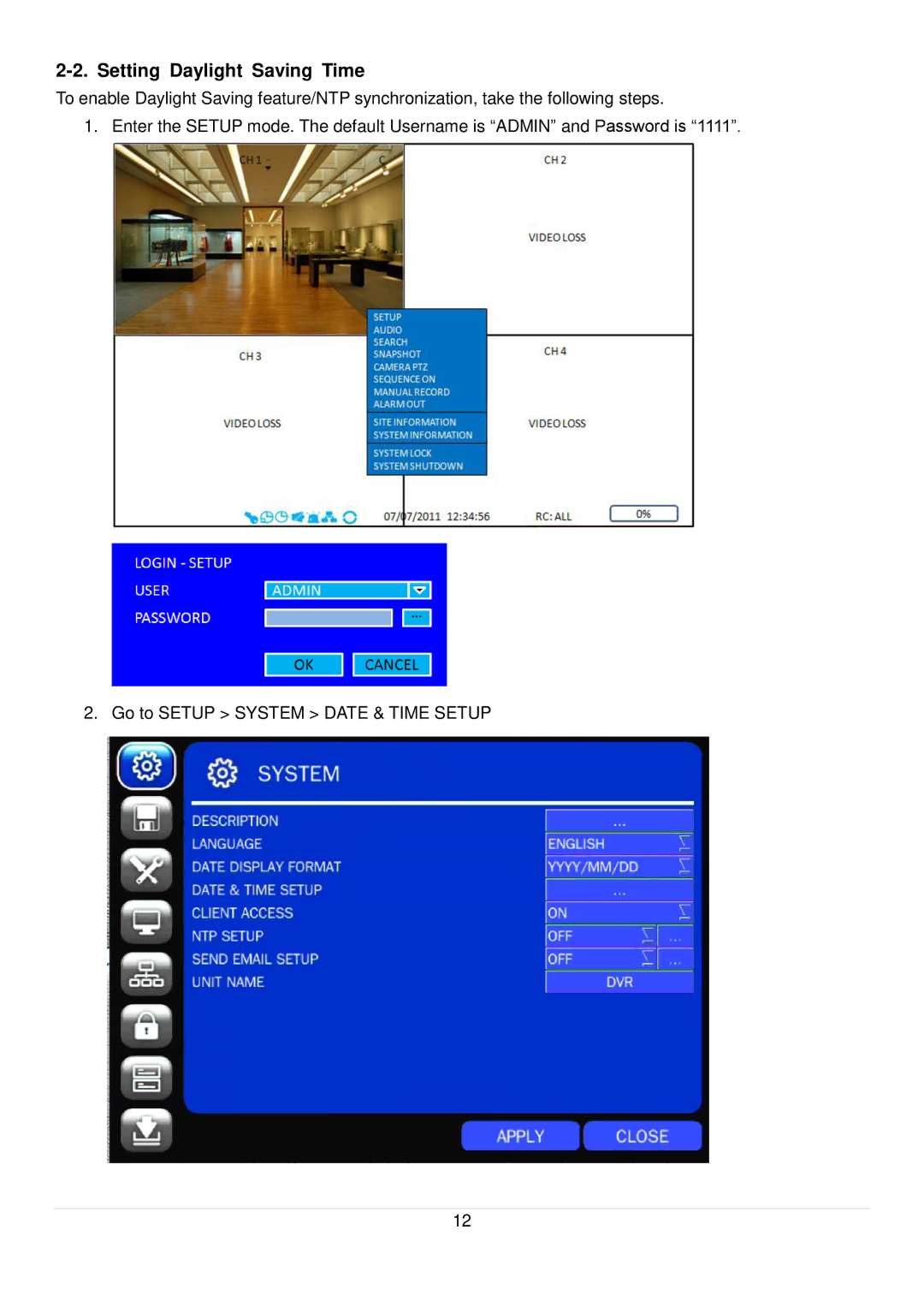
1. Enter the SETUP mode. The default Username is “ADMIN” and Password is “1111”.
2. Go to SETUP > SYSTEM > DATE & TIME SETUP
12