·3 SHORT FLASHES EVERY 2 SECONDS
A
·4 SHORT FLASHES EVERY 2 SECONDS No transducer connected.
2.4POWER CONNECTIONS
It is recommended the installation of a switch and a 5A fuse (not supplied) in the positive DC supply to the FF520. The FF520 is designed to remain in
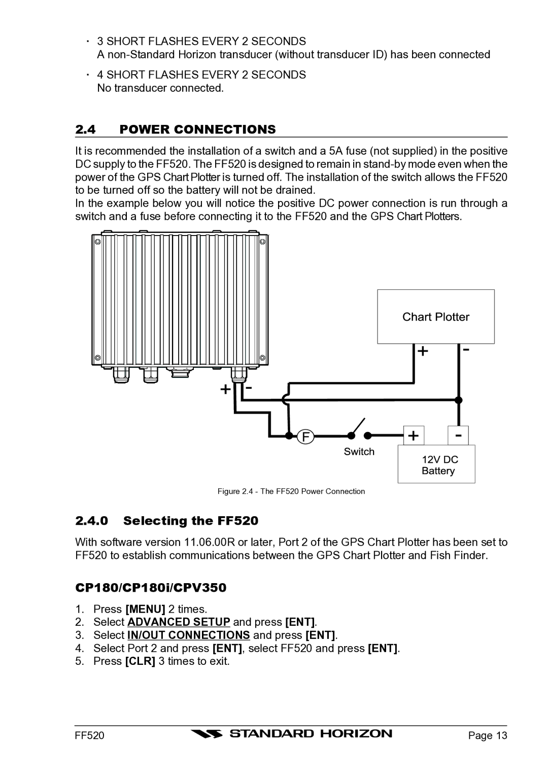
In the example below you will notice the positive DC power connection is run through a switch and a fuse before connecting it to the FF520 and the GPS Chart Plotters.
Figure 2.4 - The FF520 Power Connection
2.4.0Selecting the FF520
With software version 11.06.00R or later, Port 2 of the GPS Chart Plotter has been set to FF520 to establish communications between the GPS Chart Plotter and Fish Finder.
CP180/CP180i/CPV350
1.Press [MENU] 2 times.
2.Select ADVANCED SETUP and press [ENT].
3.Select IN/OUT CONNECTIONS and press [ENT].
4.Select Port 2 and press [ENT], select FF520 and press [ENT].
5.Press [CLR] 3 times to exit.
FF520 |
| Page 13 |
|