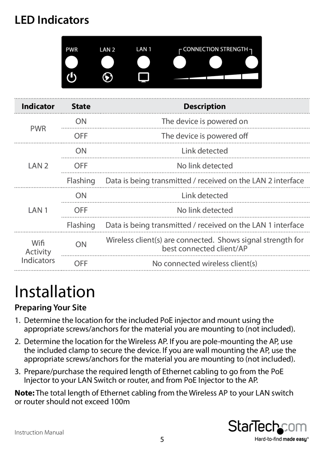
LED Indicators
Indicator | State | Description | |
PWR | ON | The device is powered on | |
OFF | The device is powered off | ||
| |||
| ON | Link detected | |
LAN 2 | OFF | No link detected | |
| Flashing | Data is being transmitted / received on the LAN 2 interface | |
| ON | Link detected | |
LAN 1 | OFF | No link detected | |
| Flashing | Data is being transmitted / received on the LAN 1 interface | |
Wifi | ON | Wireless client(s) are connected. Shows signal strength for | |
best connected client/AP | |||
Activity |
| ||
|
| ||
Indicators | OFF | No connected wireless client(s) | |
|
Installation
Preparing Your Site
1.Determine the location for the included PoE injector and mount using the appropriate screws/anchors for the material you are mounting to (not included).
2.Determine the location for the Wireless AP. If you are
3.Prepare/purchase the required length of Ethernet cabling to go from the PoE Injector to your LAN Switch or router, and from PoE Injector to the AP.
Note: The total length of Ethernet cabling from the Wireless AP to your LAN switch or router should not exceed 100m
Instruction Manual
5