;Make sure all electrical connections are tight.
3-4 Making Gas Line Connections (Gas-Fired Models Only)
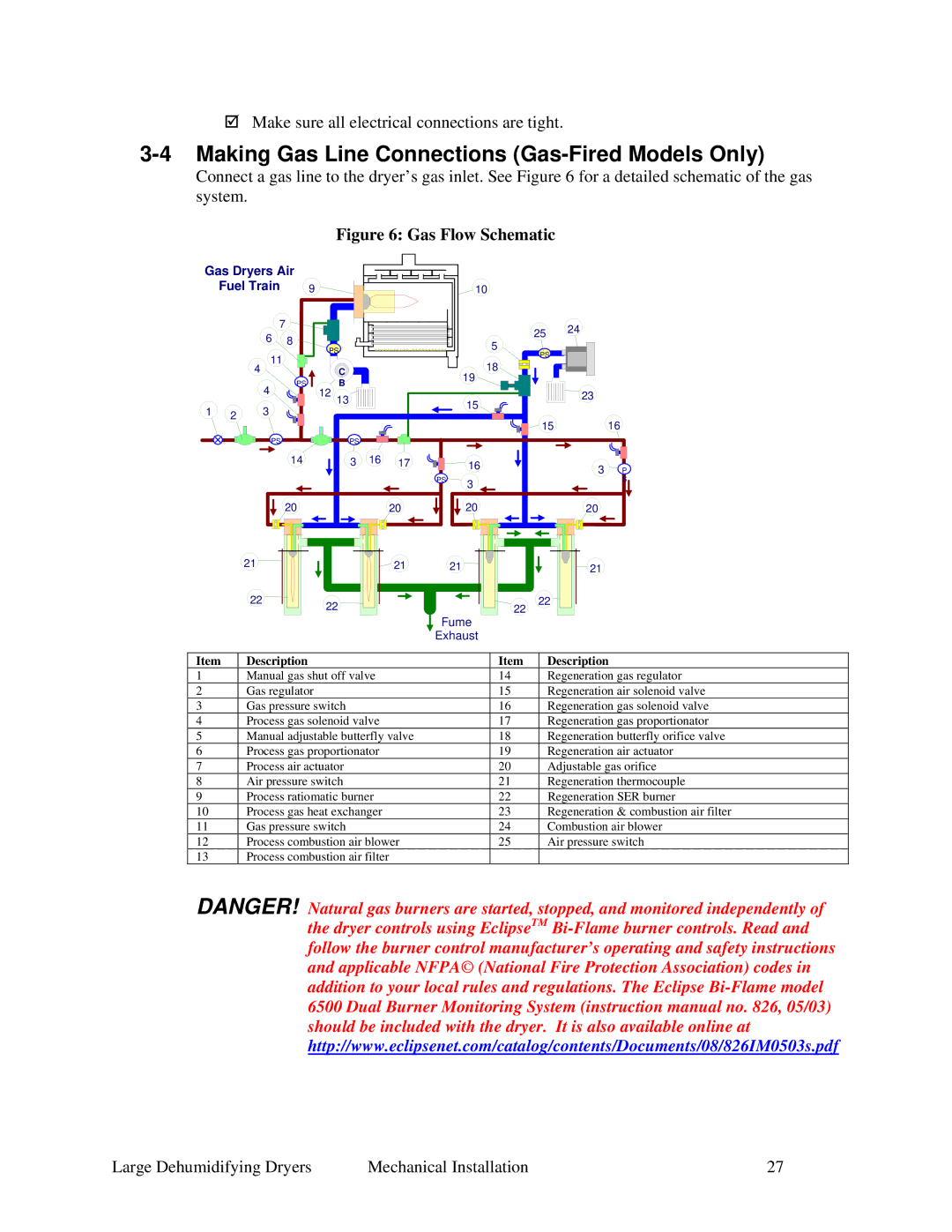
Connect a gas line to the dryer’s gas inlet. See Figure 6 for a detailed schematic of the gas system.
Figure 6: Gas Flow Schematic
Gas Dryers Air |
|
|
|
|
|
|
|
|
| |||
| Fuel Train | 9 |
|
|
|
|
| 10 |
|
|
| |
|
| 7 |
|
|
|
|
|
| 25 | 24 |
| |
|
| 6 | 8 |
|
|
|
|
|
|
| ||
|
|
|
|
|
|
| 5 |
|
| |||
|
|
|
|
|
|
|
|
|
| |||
|
| 11 | PS |
|
|
|
| PS |
|
| ||
|
|
|
|
|
|
|
|
|
|
| ||
| 4 |
|
| C |
|
|
| 18 |
|
|
| |
|
| 4 | PS |
| B |
|
|
| 19 |
|
|
|
|
| 12 | 13 |
|
|
| 15 |
| 23 |
| ||
1 |
| 3 |
|
|
|
|
|
|
| |||
2 |
|
|
|
|
|
|
|
|
| |||
|
|
|
|
|
|
| 15 |
| 16 | |||
|
|
|
|
|
|
|
|
|
|
| ||
|
| PS |
|
| PS |
|
|
|
|
|
|
|
|
|
| 14 |
| 3 | 16 | 17 |
| 16 |
| 3 | P |
|
|
|
|
|
|
|
| PS | 3 |
|
| S |
|
|
|
|
|
|
|
|
|
|
|
| |
|
|
| 20 |
|
|
| 20 |
| 20 |
| 20 |
|
| 21 |
|
|
|
|
| 21 | 21 |
|
| 21 |
|
| 22 |
| 22 |
|
|
|
| 22 | 22 |
|
| |
|
|
|
|
|
|
|
|
|
| |||
Fume
Exhaust
Item | Description | Item | Description |
1 | Manual gas shut off valve | 14 | Regeneration gas regulator |
2 | Gas regulator | 15 | Regeneration air solenoid valve |
3 | Gas pressure switch | 16 | Regeneration gas solenoid valve |
4 | Process gas solenoid valve | 17 | Regeneration gas proportionator |
5 | Manual adjustable butterfly valve | 18 | Regeneration butterfly orifice valve |
6 | Process gas proportionator | 19 | Regeneration air actuator |
7 | Process air actuator | 20 | Adjustable gas orifice |
8 | Air pressure switch | 21 | Regeneration thermocouple |
9 | Process ratiomatic burner | 22 | Regeneration SER burner |
10 | Process gas heat exchanger | 23 | Regeneration & combustion air filter |
11 | Gas pressure switch | 24 | Combustion air blower |
12 | Process combustion air blower | 25 | Air pressure switch |
13 | Process combustion air filter |
|
|
DANGER! Natural gas burners are started, stopped, and monitored independently of the dryer controls using EclipseTM
Large Dehumidifying Dryers | Mechanical Installation | 27 |
