SSE 5 BL
8.9.1. Installation of the “flap switch” signal line
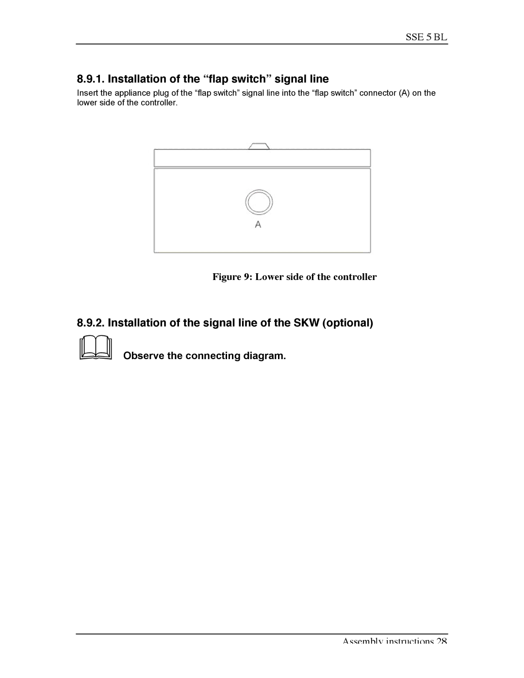
Insert the appliance plug of the “flap switch” signal line into the “flap switch” connector (A) on the lower side of the controller.
Figure 9: Lower side of the controller
8.9.2. Installation of the signal line of the SKW (optional)
&Observe the connecting diagram.
Assembly instructions 28