4-3 DESCRIPTION of GENERATOR OPERATION

4-3-1 PRIMARY EXCITING ACTION (RGV12100)

When the generator is started, the perma-

FC

nent magnet on the engine rotates to genera- tor a voltage in the exciting coil.

This voltage is regulated by a diode in the AVR to feed a current to the generator field coil. (FC). (See Fig. 4-1)

The rotor is turned an electromagnet by that current and rotates so that voltage are gener- ated in the stator coils (main coil and sub coil). The voltage generated in the sub coils is operated by the AVR to feed a current to increase the field coil current. (See Fig. 4-2) As a result, the rotor magnetism increases. This operation is repeated to generate the rated voltage at 50 Hz or 60 Hz in the main coil and DC coil.

MC

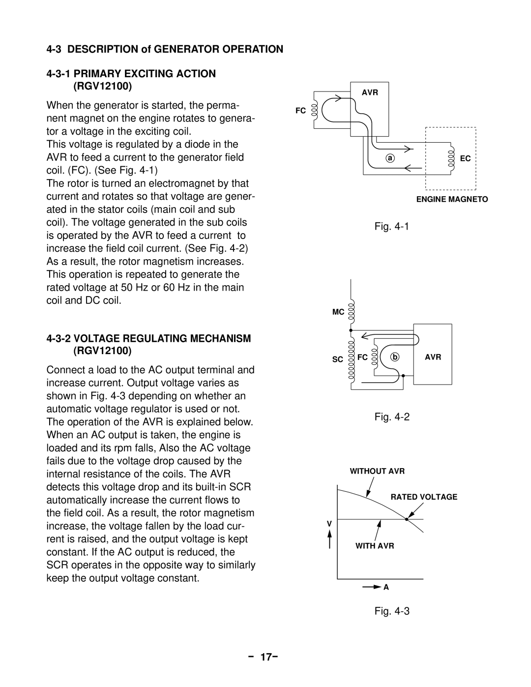
4-3-2 VOLTAGE REGULATING MECHANISM (RGV12100)

SC

AVR

aEC

ENGINE MAGNETO

Fig. 4-1

FC b AVR

Connect a load to the AC output terminal and increase current. Output voltage varies as shown in Fig. 4-3 depending on whether an automatic voltage regulator is used or not. The operation of the AVR is explained below. When an AC output is taken, the engine is loaded and its rpm falls, Also the AC voltage fails due to the voltage drop caused by the internal resistance of the coils. The AVR detects this voltage drop and its built-in SCR automatically increase the current flows to the field coil. As a result, the rotor magnetism increase, the voltage fallen by the load cur- rent is raised, and the output voltage is kept constant. If the AC output is reduced, the SCR operates in the opposite way to similarly keep the output voltage constant.

Fig. 4-2

WITHOUT AVR

RATED VOLTAGE

V

WITH AVR

A

Fig. 4-3

17

Page 20
Image 20
Subaru Robin Power Products 13100T Description of Generator Operation, Primary Exciting Action RGV12100, - 17-