4-3-3 CURRENT TRANSFORMER CONTROL (RGV13100T)
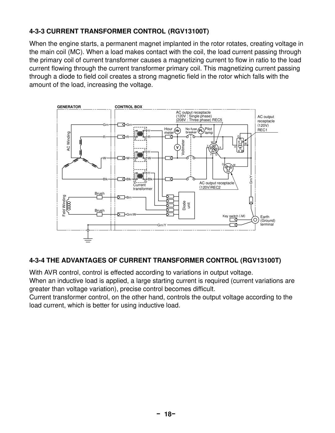
When the engine starts, a permanent magnet implanted in the rotor rotates, creating voltage in the main coil (MC). When a load makes contact with the coil, the load current passing through the primary coil of current transformer causes a magnetizing current to flow in ratio to the load current flowing through the current transformer primary coil. This magnetizing current passing through a diode to field coil creates a strong magnetic field in the rotor which falls with the amount of the load, increasing the voltage.
GENERATOR
AC Winding
CONTROL BOX
Grn | Grn |
|
|
|
|
|
| 1 | Y |
R | R | 2 | 3 R | |
|
|
| 1 | Y |
W | W | 2 | 3 W | |
|
|
| 1 | Y |
AC output receptacle
(120V : Single phase)
(208V : Three phase) REC5
Hour |
|
| Pilot |
| |
meter | Hr | Voltmeter | breaker | PL lamp |
|
|
|
| Y G |
| |
|
|
|
| W |
|
| V |
|
| Z | X |
|
|
|
|
G
AC output receptacle (120V)
REC1
G
W
H
W
Feld Winding
Blk | Blk 2 | 3 Blk |
Current transformer
Brush
Brn
Brush
Grn/W
AC output receptacle | Grn/Y |
| |
(120V)REC2 |
|
Diode unit |
|
Key switch | Earth |
| (Ground) |
Grn/Y | terminal |
4-3-4 THE ADVANTAGES OF CURRENT TRANSFORMER CONTROL (RGV13100T)
With AVR control, control is effected according to variations in output voltage.
When an inductive load is applied, a large starting current is required (current variations are greater than voltage variation), precise control becomes difficult.
Current transformer control, on the other hand, controls the output voltage according to the load current, which is better for using inductive load.
