8-5 ROTOR ASSEMBLY
1)Field coil
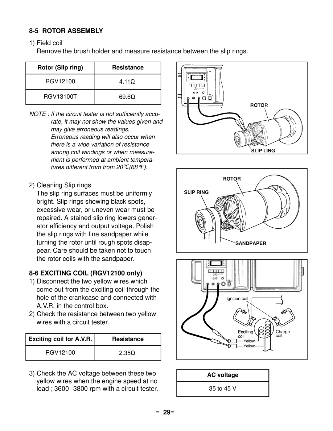
Remove the brush holder and measure resistance between the slip rings.
Rotor (Slip ring) | Resistance |
|
|
RGV12100 | 4.11Ω |
|
|
RGV13100T | 69.6Ω |
|
|
NOTE : If the circuit tester is not sufficiently accu- rate, it may not show the values given and may give erroneous readings.
Erroneous reading will also occur when there is a wide variation of resistance among coil windings or when measure- ment is performed at ambient tempera- tures different from from 20℃(68 °F).
2)Cleaning Slip rings
The slip ring surfaces must be uniformly bright. Slip rings showing black spots, excessive wear, or uneven wear must be repaired. A stained slip ring lowers gener- ator efficiency and output voltage. Polish the slip rings with fine sandpaper while turning the rotor until rough spots disap- pear. Care should be taken not to touch the rotor coils with the sandpaper.
8-6 EXCITING COIL (RGV12100 only)
1)Disconnect the two yellow wires which come out from the exciting coil through the hole of the crankcase and connected with A.V.R. in the control box.
2)Check the resistance between two yellow wires with a circuit tester.
Exciting coil for A.V.R. | Resistance |
|
|
RGV12100 | 2.35Ω |
|
|
3)Check the AC voltage between these two yellow wires when the engine speed at no load ;
ROTOR
SLIP RING
SANDPAPER |
|
Ignitioncoil |
|
ExcitingcoilYellow | Chargecoil |
AC voltage
35 to 45 V