Revision A, August
USA 650 960-1300 fax 650
Revision A, August
Please Recycle
Contents
Running Diagnostics Tests
Index
Regulatory Compliance Statements
Page
How This Book Is Organized
Preface
Related Documents
Unix Commands
Shell Prompts
Typographic Conventions
Table P-1SunExpress Contact Information
Ordering Sun Documents
Xii
Sun Welcomes Your Comments
Page
1Sun Quad FastEthernet PCI adapter
Product Overview
Hardware and Software Requirements
Features
1Hardware and Software Requirements
Displaying the OpenBoot Prom Revision Level
Checking the OpenBoot Prom Revision Level
Page
Using a text editor, add the following line to the end
Installing the Adapter
Adding an Entry to the driveraliases File
Installing the Adapter
Diagnostic Testing
Verifying the Installation
Examining Network Activity
Code Example 2-1 watch-net-allCommad Output
Perform a reconfiguration boot on the system
Rebooting the System
Page
At the command line, use the grep command to search
Installing the Driver Software
Configuring the Driver Software
Configuring the Host Files
Etc/hosts file
Reboot your system
Booting From the Network
At the ok prompt type
Configuring Driver Parameters
Post-Installation Procedures Optional
Increasing TCP/IP Performance
As superuser root, type
Type
Forcing Network Speed Between 10 Mbps and 100 Mbps
Local-mac-address Property
Auto-Negotiation
Ok setenv local-mac-address? true
Page
Table A-1Physical Dimensions
Specifications Physical Dimensions
Table A-2Power Requirements
Power Requirements
Performance Specifications
Table A-3Performance Specifications
Specifications
Page
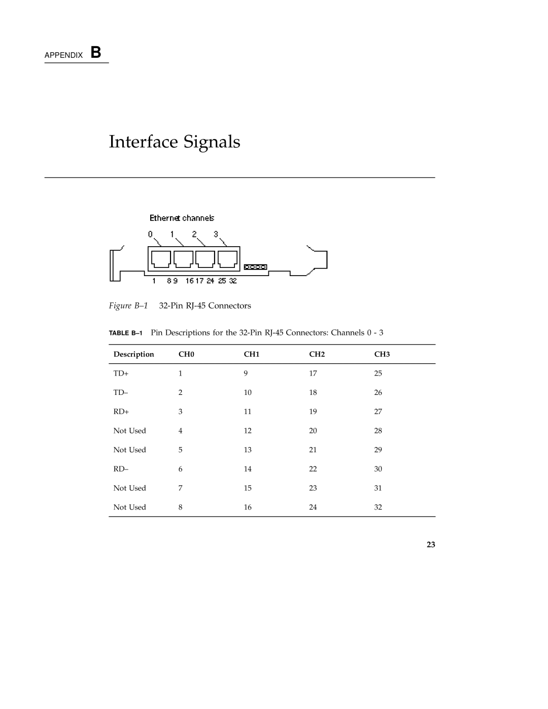
Figure B-132-Pin RJ-45 Connectors
Interface Signals
Page
Internal Transceiver
Configuring the Quad FastEthernet Device Driver Parameters
Table C-1qfe Driver Parameter, Status, and Descriptions
Driver Parameter Values and Definitions
Qfe Driver Parameter, Status, and Descriptions
Defining the Current Status
Table C-2Read-Only Parameters Defining the Current Status
Inter-Packet Gap Parameters
Packet after receiving a packet
Table C-4Parameters Defining lancemode and ipg0
Table C-5Operational Mode Parameters
Operational Mode Parameters
Reporting Transceiver Capabilities
Defining the Number of Back-to-Back Packets to Transmit
Table C-6Back-to-back Packet Transmission Capability
Table C-7Read-Only Transceiver Capabilities
Table C-8Read-Only Link Partner Capabilities
Reporting the Link Partner Capabilities
Setting Parameters Using the ndd Utility
Setting qfe Driver Parameters
To Specify the Device Instance for the ndd Utility
To modify a parameter value, use the -setoption
Use the instance number to select the device
Using the ndd Utility in Interactive Mode
Select at least one of the five capabilities adv100fdxcap
To Set the Mode to Auto-Negotiation
Table C-9Setting Variables in the /etc/system File
Setting Parameters in the /etc/system File
Setting Parameters Using the qfe.conf File
Unit-address = 2,1 Fourth line in the previous example
Setting ipg Driver Parameters Using a qfe.conf File
Kernel/drv/qfe.conf file
Set the ipg1 and ipg2 parameters for the above four devices
Using the OpenBoot Prom FCode Selftest
Running Diagnostics Tests
Shut down the system
Reset the system
Type show-devsto display the list of devices
Reset and reboot the system
Set the auto-boot?configuration parameter to true
Page
FCC Class a Notice
Regulatory Compliance Statements
FCC Class B Notice
DOC Class B Notice Avis DOC, Classe B
DOC Class a Notice Avis DOC, Classe a
EMC
Declaration of Conformity
Supplementary Information
Safety
Page
Index-51
Index