AIR CONDITIONER DIAGRAM
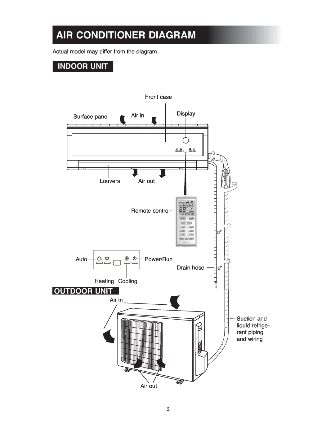
Actual model may differ from the diagram
INDOOR UNIT
|
|
| Front case | ||||
Surface panel | Air in |
| Display | ||||
| |||||||
|
|
|
|
| |||
|
|
|
|
|
|
|
|
|
|
|
|
|
|
|
|
|
|
|
|
|
|
|
|
|
|
|
|
|
|
|
|
Louvers | Air out |
| Remote control |
Auto
Power/Run
Drain hose
Heating Cooling
OUTDOOR UNIT
Air in
![]()
![]() Suction and
Suction and
liquid refrige- rant piping and wiring
Air out
3