Chapter 5: Advanced Motherboard Setup
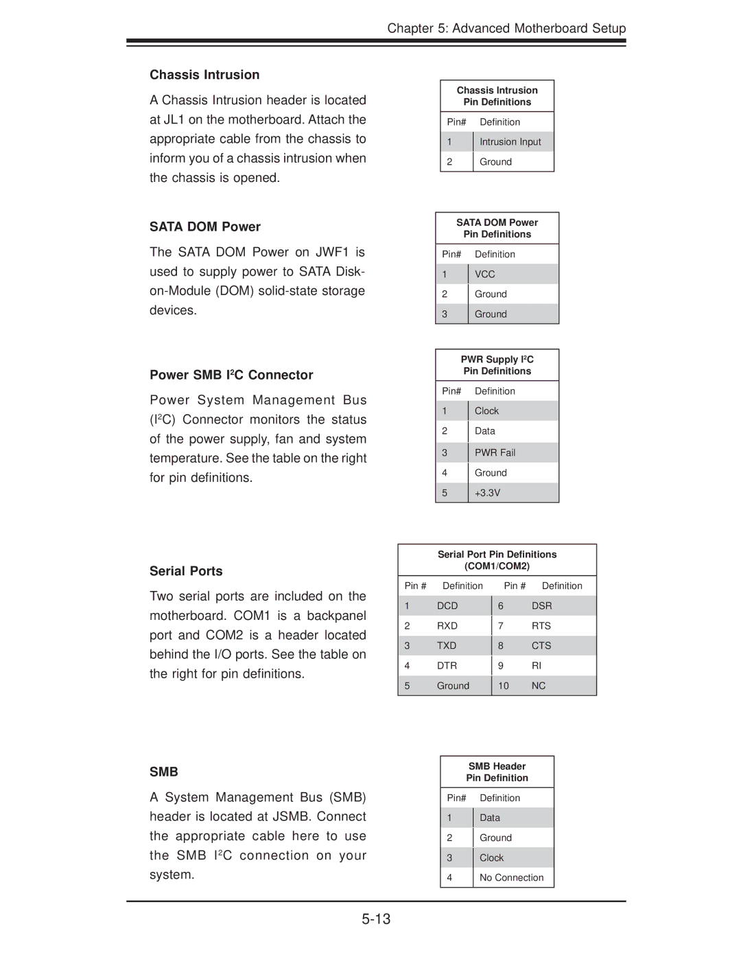
Chassis Intrusion
A Chassis Intrusion header is located at JL1 on the motherboard. Attach the appropriate cable from the chassis to inform you of a chassis intrusion when the chassis is opened.
SATA DOM Power
The SATA DOM Power on JWF1 is used to supply power to SATA Disk-
Power SMB I2C Connector
Power System Management Bus (I2C) Connector monitors the status of the power supply, fan and system temperature. See the table on the right for pin definitions.
Serial Ports
Chassis Intrusion
Pin Definitions
Pin# Definition
1Intrusion Input
2Ground
SATA DOM Power
Pin Definitions
Pin# Definition
1VCC
2Ground
3Ground
PWR Supply I2C
Pin Definitions
Pin# Definition
1Clock
2Data
3PWR Fail
4Ground
5+3.3V
Serial Port Pin Definitions
(COM1/COM2)
Two serial ports are included on the motherboard. COM1 is a backpanel port and COM2 is a header located behind the I/O ports. See the table on the right for pin definitions.
Pin # Definition
1DCD
2RXD
3TXD
4DTR
5Ground
Pin # Definition
6DSR
7RTS
8CTS
9RI
10NC
SMB
A System Management Bus (SMB) header is located at JSMB. Connect the appropriate cable here to use the SMB I2C connection on your system.
SMB Header
Pin Definition
Pin# Definition
1Data
2Ground
3Clock
4No Connection