SUPERSERVER
5-9 Connector Definitions
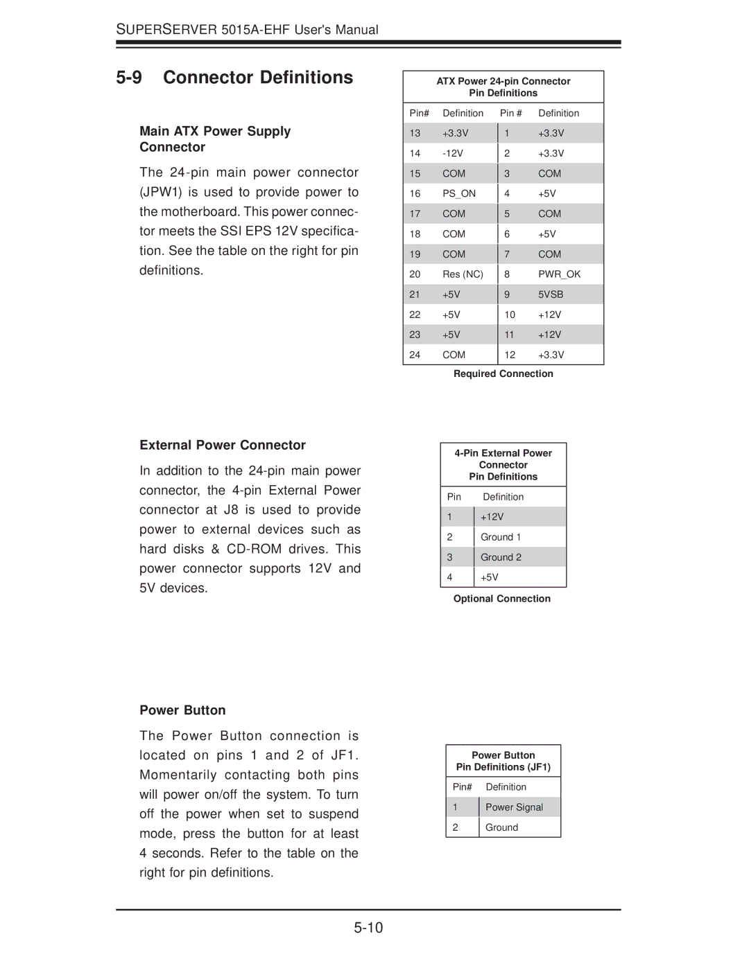
ATX Power
Pin Definitions
Main ATX Power Supply
Connector
The
Pin# Definition
13+3.3V
14
15COM
16PS_ON
17COM
18COM
19COM
20Res (NC)
21+5V
22+5V
23+5V
24COM
Pin # Definition
1+3.3V
2+3.3V
3COM
4+5V
5COM
6+5V
7COM
8PWR_OK
95VSB
10+12V
11+12V
12+3.3V
Required Connection
External Power Connector
In addition to the
Power Button
The Power Button connection is located on pins 1 and 2 of JF1. Momentarily contacting both pins will power on/off the system. To turn off the power when set to suspend mode, press the button for at least 4 seconds. Refer to the table on the right for pin definitions.
Connector
Pin Definitions
Pin Definition
1+12V
2Ground 1
3Ground 2
4+5V
Optional Connection
Power Button
Pin Definitions (JF1)
Pin# Definition
1Power Signal
2Ground