SUPERSERVER
Power LED
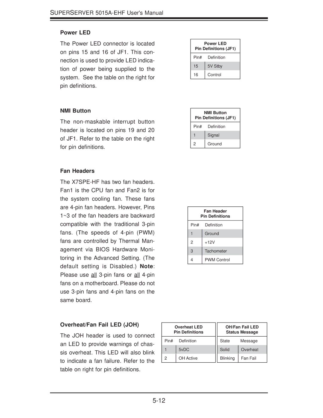
The Power LED connector is located on pins 15 and 16 of JF1. This con- nection is used to provide LED indica- tion of power being supplied to the system. See the table on the right for pin definitions.
NMI Button
The
Fan Headers
The
Power LED
Pin Definitions (JF1)
Pin# Definition
155V Stby
16Control
NMI Button
Pin Definitions (JF1)
Pin# Definition
1Signal
2Ground
Fan Header
Pin Definitions
Pin# Definition
1Ground
2+12V
3Tachometer
4PWM Control
Overheat/Fan Fail LED (JOH)
The JOH header is used to connect an LED to provide warnings of chas- sis overheat. This LED will also blink to indicate a fan failure. Refer to the table on right for pin definitions.
Overheat LED Pin Definitions
Pin# Definition
15vDC
2OH Active
OH/Fan Fail LED
Status Message
State |
| Message |
Solid |
| Overheat |
| ||
Blinking |
| Fan Fail |
| ||
|
|
|