Vertex Standard FT-1000MP manual Safety Precautions, Power Connections, Ground Connections

Models: FT-1000MP

1 119
Download 119 pages 809 b
Page 9
Image 9

Before initiating the installation of your MARK-V FT- 1000MP transceiver, please take the time to review the following safety guidelines.

POWER CONNECTIONS

We strongly recommend that AC power for your MARK-VFT-1000MPbe provided only from the sup- plied FP-29AC Power Supply, so as to ensure that the voltage and current requirements of the MARK-V FT- 1000MP are fully met.

If you do need to provide DC power to your MARK- V FT-1000MP, on an emergency basis, from a power source other than the FP-29, please be absolutely cer- tain to observe proper connections in your wiring. Note that other manufacturers may use the same type of DC power connector as does Yaesu, but the wiring con- figuration of the other manufacturer’s plug will almost certainly be different from that specified for your trans- ceiver. The correct wiring diagram is shown below.

GROUND CONNECTIONS

The MARK-VFT-1000MPHF transceiver, like any other HF communications apparatus, requires an ef- fective ground system for maximum electrical safety and best communications effectiveness. A good ground system can contribute to station efficiency in a number of ways:

rIt can minimize the possibility of electrical shock to the operator.

rIt can minimize RF currents flowing on the shield of the coaxial cable and the chassis of the transceiver; such currents may lead to radiation which can cause interference to home entertainment devices or labo- ratory test equipment.

rIt can minimize the possibility of erratic transceiver/ accessory operation caused by RF feedback and/ or improper current flow through logic devices.

An effective earth ground system make take sev- eral forms; for a more complete discussion, see an appropriate RF engineering text. The information be- low is intended only as a guideline.

SAFETY PRECAUTIONS

Typically, the ground connection consists of one or more copper-clad steel rods, driven into the ground. If multiple ground rods are used, they should be posi- tioned in a “V” configuration, and bonded together at the apex of the “V” which is nearest the station loca- tion. Use a heavy, braided cable (such as the discarded shield from type RG-213 coaxial cable) and strong cable clamps to secure the braided cable(s) to the ground rods. Be sure to weatherproof the connections to ensure many years of reliable service. Use the same type of heavy, braided cable for the connections to the station ground bus (described below).

Inside the station, a common ground bus consist- ing of a copper pipe of at least 25 mm (1”) diameter should be used. An alternative station ground bus may consist of a wide copper plate (single-sided circuit board material is ideal) secured to the bottom of the operat- ing desk. Grounding connections from individual de- vices such as transceivers, power supplies, and data communications devices (TNCs, etc.) should be made directly to the ground bus using a heavy, braided cable.

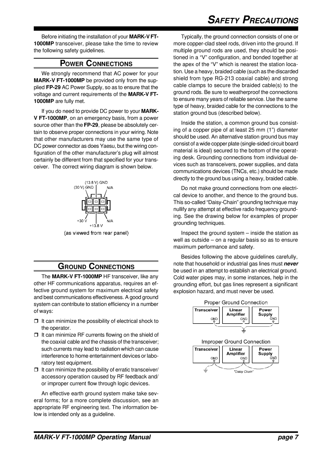
Do not make ground connections from one electri- cal device to another, and thence to the ground bus. This so-called “Daisy-Chain” grounding technique may nullify any attempt at effective radio frequency ground- ing. See the drawing below for examples of proper grounding techniques.

Inspect the ground system – inside the station as well as outside – on a regular basis so as to ensure maximum performance and safety.

Besides following the above guidelines carefully, note that household or industrial gas lines must never be used in an attempt to establish an electrical ground. Cold water pipes may, in some instances, help in the grounding effort, but gas lines represent a significant explosion hazard, and must never be used.

MARK-V FT-1000MP Operating Manual

page 7

Page 9
Image 9
Vertex Standard FT-1000MP manual Safety Precautions, Power Connections, Ground Connections