Advanced Features
EDSP
EDSP NOISE REDUCER
Noise reduction is accomplished ![]() by utilization of one of the four set-
by utilization of one of the four set- ![]()
![]() tings selected by the front panel [NR]
tings selected by the front panel [NR] ![]()
![]()
![]()
![]() button. Press the [NR] button to toggle
button. Press the [NR] button to toggle ![]()
![]()
![]()
![]() between Noise Reduction “A,” “B,”
between Noise Reduction “A,” “B,” ![]()
![]()
![]()
![]() “C,” “D,” and “OFF.” Each setting has
“C,” “D,” and “OFF.” Each setting has ![]()
![]()
![]()
![]() correlation parameters optimized to
correlation parameters optimized to ![]()
![]()
![]()
![]() reduce random noise, static, pulse/
reduce random noise, static, pulse/ ![]()
![]()
![]()
![]()
![]()
![]()
![]()
![]()
![]() with little degradation of the desired
with little degradation of the desired ![]()
![]()
![]()
![]()
![]()
![]()
![]() signal. As with the Contour feature, it
signal. As with the Contour feature, it ![]() is difficult to predict which setting will be most effective under current noise conditions, so experiment with the settings as conditions change.
is difficult to predict which setting will be most effective under current noise conditions, so experiment with the settings as conditions change.
EDSP APF (AUDIO PEAK FILTER)
In the CW mode, the front [APF] button sets the bandwidth of the EDSP’s CW peaking filter. Press the [APF] button repeatedly to toggle be- tween bandwidth selections “240 Hz,” “120 Hz,” “60 Hz,” “DATA” (which is optimized bandwidth for FAX, PACKET or SSTV operation), and “OFF.”
IDBT
(INTERLOCKED DIGITAL BANDWIDTH TRACKING) SYSTEM
You can control the EDSP Contour’s “Bandpass” filter characteristics according to the SHIFT and WIDTH knobs’ settings. To do this, press the [IDBT] button on the right side of the Shuttle Jog to activate the IDBS feature. Doing so will automatically program the band- width of the Bandpass Contour filter to match the IF bandwidth set by these two controls; therefore, if you have narrowed the IF passband to 1.9 kHz using the WIDTH and SHIFT controls, the IDBT feature will au- tomatically set the Contour filter’s Bandpass mode to 1.9 kHz, as well.
EDSP AUTO MULTIPLE NOTCH FILTER
On page 48, we previously discussed basic IF notch filter operation and how it is used to attenuate hetero- dynes. EDSP offers
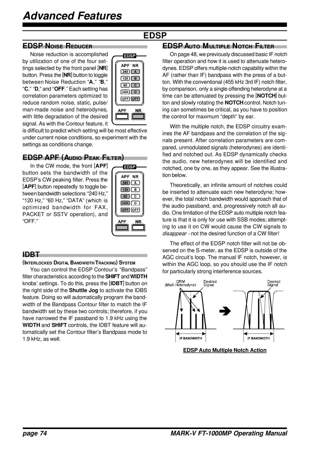
With the multiple notch, the EDSP circuitry exam- ines the AF bandpass and the correlation of the sig- nals present. After correlation parameters are com- pared, unmodulated signals (heterodynes) are identi- fied and notched out. As EDSP dynamically checks the audio, new heterodynes will be identified and notched, one by one, as they appear. See the illustra- tion below.
Theoretically, an infinite amount of notches could be inserted to attenuate each new heterodyne; how- ever, the total notch bandwidth would approach that of the audio passband, and, progressively notch all au- dio. One limitation of the EDSP auto multiple notch fea- ture is that it is only for use with SSB modes; attempt- ing to use it on CW would cause the CW signals to disappear - not the desired function of a CW filter!
The effect of the EDSP notch filter will not be ob- served on the
EDSP Auto Multiple Notch Action
page 74 |
|
