CAT System Computer Control
DOWNLOADING
MARK-V FT-1000MP DATA
On command, the
The following four commands cause the
Status Update (10H) - causes the transceiver to return all or portions of its RAM table (up to 1,863 bytes).
Status Flags Request (FAH) - obtains only the first 6 bytes (the Status Flags), plus 2 extra “Model ID” bytes (10H and 00H).
Read Meter (F7H) - returns the meter deflection (0
-FFH) repeated in four bytes, followed by one “filler” byte (F7H).
Pacing Command (0EH) - Each byte of returned data may be delayed by an interval determined by this command (0 to 255 ms in
Note: Pacing allows returned data to be read and processed by slower computers. However, set it as short as your computer will allow, to minimize the inconvenience of the delay. Sending all 1,863 bytes requires just under 5 seconds with zero- length delay selected, but over 5 minutes if the maximum delay is selected!
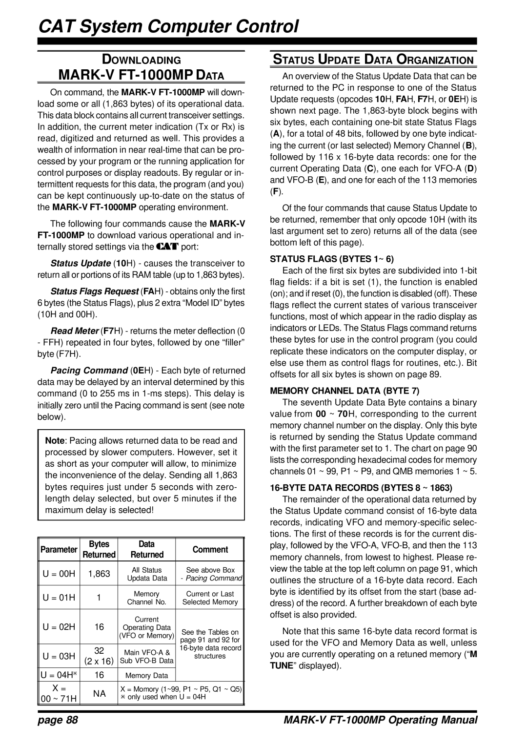
| Parameter | Bytes | Data | Comment |
|
| Returned | Returned |
| ||
| U = 00H | 1,863 | All Status | See above Box |
|
| Updata Data | - Pacing Command |
| ||
|
|
|
| ||
|
|
|
|
|
|
| U = 01H | 1 | Memory | Current or Last |
|
| Channel No. | Selected Memory |
| ||
|
|
|
| ||
|
|
|
|
|
|
| U = 02H | 16 | Current |
|
|
| Operating Data | See the Tables on |
| ||
|
|
| (VFO or Memory) |
| |
|
|
| page 91 and 92 for |
| |
| U = 03H | 32 | Main |
| |
| structures |
| |||
| (2 x 16) | Sub |
| ||
|
|
|
| ||
|
|
|
|
|
|
| U = 04Hø | 16 | Memory Data |
|
|
| X = | NA | X = Momory (1~99, P1 ~ P5, Q1 ~ Q5) |
| |
| 00 ~ 71H | ø only used when U = 04H |
| ||
|
|
| |||
|
|
|
|
|
|
STATUS UPDATE DATA ORGANIZATION
An overview of the Status Update Data that can be returned to the PC in response to one of the Status Update requests (opcodes 10H, FAH, F7H, or 0EH) is shown next page. The
Of the four commands that cause Status Update to be returned, remember that only opcode 10H (with its last argument set to zero) returns all of the data (see bottom left of this page).
STATUS FLAGS (BYTES 1~ 6)
Each of the first six bytes are subdivided into
MEMORY CHANNEL DATA (BYTE 7)
The seventh Update Data Byte contains a binary value from 00 ~ 70H, corresponding to the current memory channel number on the display. Only this byte is returned by sending the Status Update command with the first parameter set to 1. The chart on page 90 lists the corresponding hexadecimal codes for memory channels 01 ~ 99, P1 ~ P9, and QMB memories 1 ~ 5.
16-BYTE DATA RECORDS (BYTES 8 ~ 1863)
The remainder of the operational data returned by the Status Update command consist of
Note that this same
page 88 |
|