REAR PANEL CONTROLS & CONNECTORS

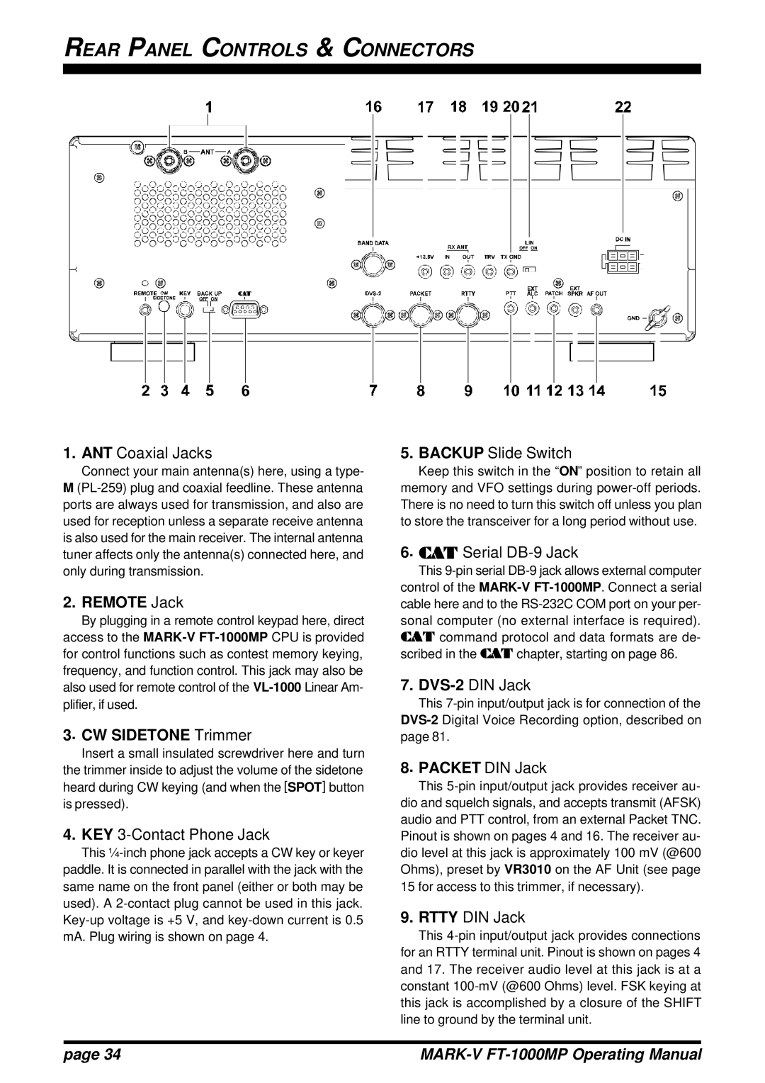
1.ANT Coaxial Jacks

Connect your main antenna(s) here, using a type- M (PL-259) plug and coaxial feedline. These antenna ports are always used for transmission, and also are used for reception unless a separate receive antenna is also used for the main receiver. The internal antenna tuner affects only the antenna(s) connected here, and only during transmission.

2. REMOTE Jack

By plugging in a remote control keypad here, direct access to the MARK-VFT-1000MPCPU is provided for control functions such as contest memory keying, frequency, and function control. This jack may also be also used for remote control of the VL-1000Linear Am- plifier, if used.

3. CW SIDETONE Trimmer

Insert a small insulated screwdriver here and turn the trimmer inside to adjust the volume of the sidetone heard during CW keying (and when the [SPOT] button is pressed).

4.KEY 3-Contact Phone Jack

This ¼-inch phone jack accepts a CW key or keyer paddle. It is connected in parallel with the jack with the same name on the front panel (either or both may be used). A 2-contact plug cannot be used in this jack. Key-up voltage is +5 V, and key-down current is 0.5 mA. Plug wiring is shown on page 4.

5.BACKUP Slide Switch

Keep this switch in the “ON” position to retain all memory and VFO settings during power-off periods. There is no need to turn this switch off unless you plan to store the transceiver for a long period without use.

6. CAT Serial DB-9 Jack

This 9-pin serial DB-9 jack allows external computer control of the MARK-VFT-1000MP. Connect a serial cable here and to the RS-232C COM port on your per- sonal computer (no external interface is required). CAT command protocol and data formats are de- scribed in the CAT chapter, starting on page 86.

7.DVS-2DIN Jack

This 7-pin input/output jack is for connection of the DVS-2Digital Voice Recording option, described on page 81.

8. PACKET DIN Jack

This 5-pin input/output jack provides receiver au- dio and squelch signals, and accepts transmit (AFSK) audio and PTT control, from an external Packet TNC. Pinout is shown on pages 4 and 16. The receiver au- dio level at this jack is approximately 100 mV (@600 Ohms), preset by VR3010 on the AF Unit (see page 15 for access to this trimmer, if necessary).

9.RTTY DIN Jack

This 4-pin input/output jack provides connections for an RTTY terminal unit. Pinout is shown on pages 4 and 17. The receiver audio level at this jack is at a constant 100-mV (@600 Ohms) level. FSK keying at this jack is accomplished by a closure of the SHIFT line to ground by the terminal unit.

page 34

MARK-V FT-1000MP Operating Manual

Page 36
Image 36
Vertex Standard FT-1000MP manual Rear Panel Controls & Connectors, Remote Jack, CW Sidetone Trimmer, Packet DIN Jack