CAT System Computer Control
CONSTRUCTING AND SENDING CAT COMMANDS
Example #1: Set Main
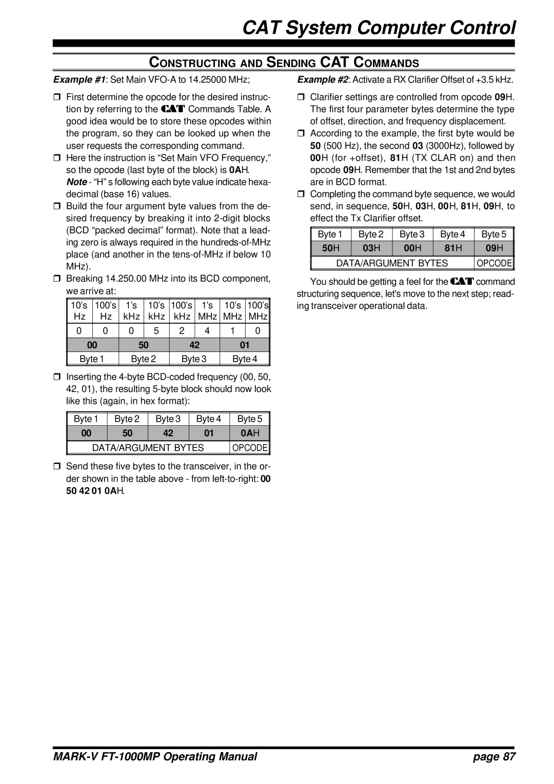
rFirst determine the opcode for the desired instruc- tion by referring to the CAT Commands Table. A good idea would be to store these opcodes within the program, so they can be looked up when the user requests the corresponding command.
rHere the instruction is “Set Main VFO Frequency,” so the opcode (last byte of the block) is 0AH. Note - “H” s following each byte value indicate hexa- decimal (base 16) values.
rBuild the four argument byte values from the de- sired frequency by breaking it into
rBreaking 14.250.00 MHz into its BCD component, we arrive at:
| 10’s | 100’s | 1’s | 10’s | 100’s | 1’s | 10’s | 100’s |
| Hz | Hz | kHz | kHz | kHz | MHz | MHz | MHz |
| 0 | 0 | 0 | 5 | 2 | 4 | 1 | 0 |
|
|
|
|
|
|
|
|
|
| 00 | 50 | 42 | 01 | ||||
| Byte 1 | Byte 2 | Byte 3 | Byte 4 | ||||
|
|
|
|
|
|
|
|
|
Example #2: Activate a RX Clarifier Offset of +3.5 kHz.
rClarifier settings are controlled from opcode 09H. The first four parameter bytes determine the type of offset, direction, and frequency displacement.
rAccording to the example, the first byte would be 50 (500 Hz), the second 03 (3000Hz), followed by 00H (for +offset), 81H (TX CLAR on) and then opcode 09H. Remember that the 1st and 2nd bytes are in BCD format.
rCompleting the command byte sequence, we would send, in sequence, 50H, 03H, 00H, 81H, 09H, to effect the Tx Clarifier offset.
| Byte 1 | Byte 2 | Byte 3 | Byte 4 | Byte 5 |
|
| 50H | 03H | 00H | 81H | 09H |
|
|
|
|
|
|
|
|
| DATA/ARGUMENT BYTES | OPCODE |
| |||
|
|
|
|
|
|
|
You should be getting a feel for the CAT command structuring sequence, let's move to the next step; read- ing transceiver operational data.
rInserting the
| Byte 1 | Byte 2 | Byte 3 | Byte 4 | Byte 5 |
| 00 | 50 | 42 | 01 | 0AH |
| DATA/ARGUMENT BYTES | OPCODE | |||
|
|
|
|
|
|
rSend these five bytes to the transceiver, in the or- der shown in the table above - from
| page 87 |
