Installing Internal Accessories
MAIN RECEIVER 2ND AND 3RD IF FILTERS
A total of 5 optional crystal IF filter units can be in- stalled in addition to the
Important! After filter installation,
Filter Installation
rDisconnect all cables from the transceiver.
rReferring to Figure 1, remove the four screws (ð) on each side of the transceiver, and the seven screws (ž) from the bottom of the transceiver, then lift off the bottom cover.
rReferring to Figure 2, remove the six screws (Æ) from the top panel. Pry the top cover open and dis- connect the speaker cable from the speaker, then lift off the top and side covers.
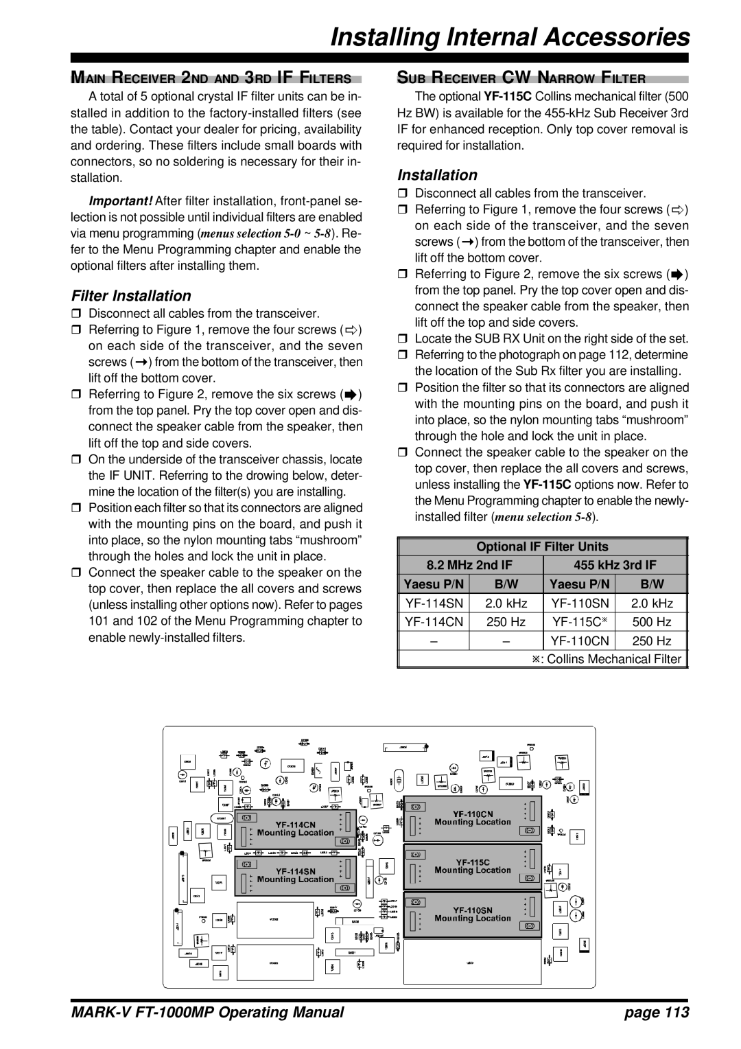
rOn the underside of the transceiver chassis, locate the IF UNIT. Referring to the drowing below, deter- mine the location of the filter(s) you are installing.
rPosition each filter so that its connectors are aligned with the mounting pins on the board, and push it into place, so the nylon mounting tabs “mushroom” through the holes and lock the unit in place.
rConnect the speaker cable to the speaker on the top cover, then replace the all covers and screws (unless installing other options now). Refer to pages 101 and 102 of the Menu Programming chapter to enable
SUB RECEIVER CW NARROW FILTER
The optional
Installation
rDisconnect all cables from the transceiver.
rReferring to Figure 1, remove the four screws (ð) on each side of the transceiver, and the seven screws (ž) from the bottom of the transceiver, then lift off the bottom cover.
rReferring to Figure 2, remove the six screws (Æ) from the top panel. Pry the top cover open and dis- connect the speaker cable from the speaker, then lift off the top and side covers.
rLocate the SUB RX Unit on the right side of the set.
rReferring to the photograph on page 112, determine the location of the Sub Rx filter you are installing.
rPosition the filter so that its connectors are aligned with the mounting pins on the board, and push it into place, so the nylon mounting tabs “mushroom” through the hole and lock the unit in place.
rConnect the speaker cable to the speaker on the top cover, then replace the all covers and screws, unless installing the
Optional IF Filter Units
8.2 MHz 2nd IF | 455 kHz 3rd IF | ||
Yaesu P/N | B/W | Yaesu P/N | B/W |
2.0 kHz | 2.0 kHz | ||
|
|
|
|
250 Hz | 500 Hz | ||
– | – | 250 Hz | |
|
|
|
|
ø: Collins Mechanical Filter
| page 113 |
