Vertex Standard FT-1000MP General Setup, FP-29, Preliminary Inspection, Transceiver Location

Models: FT-1000MP

1 119
Download 119 pages 809 b
Page 11
Image 11

PRELIMINARY INSPECTION

Inspect the transceiver upon opening the packing carton. Check that all controls and switches work freely, and inspect the cabinet for any damage. Ensure the accessory fuses and plugs pictured on page 4 are in- cluded. If any damage is found, document it completely, and contact the shipping company (or dealer, if you purchased it
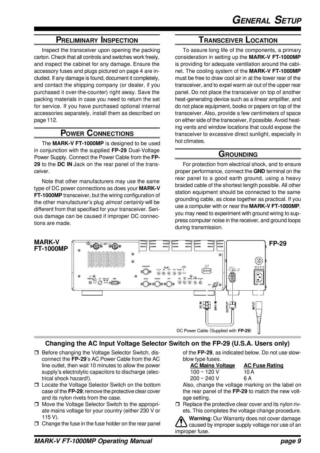
 over-the-counter) right away. Save the packing materials in case you need to return the set for service. If you have purchased optional internal accessories separately, install them as described on page 112.

POWER CONNECTIONS

The MARK-VFT-1000MPis designed to be used in conjunction with the supplied FP-29Dual-Voltage Power Supply. Connect the Power Cable from the FP- 29 to the DC IN Jack on the rear panel of the trans- ceiver.

Note that other manufacturers may use the same type of DC power connections as does your MARK-VFT-1000MPtransceiver, but the wiring configuration of the other manufacturer’s plug almost certainly will be different from that specified for your transceiver. Seri- ous damage can be caused if improper DC connec- tions are made.

GENERAL SETUP

TRANSCEIVER LOCATION

To assure long life of the components, a primary consideration in setting up the MARK-VFT-1000MPis providing for adequate ventilation around the cabi- net. The cooling system of the MARK-VFT-1000MPmust be free to draw cool air in at the lower rear of the transceiver, and to expel warm air out of the upper rear panel. Do not place the transceiver on top of another heat-generating device such as a linear amplifier, and do not place equipment, books or papers on top of the transceiver. Also, provide a few centimeters of space on either side of the transceiver, if possible. Avoid heat- ing vents and window locations that could expose the transceiver to excessive direct sunlight, especially in hot climates.

GROUNDING

For protection from electrical shock, and to ensure proper performance, connect the GND terminal on the rear panel to a good earth ground, using a heavy braided cable of the shortest length possible. All other station equipment should be connected to the same grounding cable, as close together as practical. If you use a computer with or near the MARK-VFT-1000MP, you may need to experiment with ground wiring to sup- press computer noise in the receiver, and ground loops during transmission.

MARK-V FT-1000MP

FP-29

DC Power Cable (Supplied with FP-29)

Changing the AC Input Voltage Selector Switch on the FP-29 (U.S.A. Users only)

rBefore changing the Voltage Selector Switch, dis- connect the FP-29’s AC Power Cable from the AC line outlet, then wait 10 minutes to allow the power supply’s electrolytic capacitors to discharge (elec- trical shock hazard!).

rLocate the Voltage Selector Switch on the bottom case of the FP-29; remove the protective clear cover and its nylon rivets from the case.

rMove the Voltage Selector Switch to the appropri- ate mains voltage for your country (either 230 V or 115 V).

rChange the fuse in the fuse holder on the rear panel

of the FP-29, as indicated below. Do not use slow-

blow type fuses.


AC Mains Voltage

AC Fuse Rating

100 ~ 120 V

10 A

200 ~ 240 V

6 A

Also, change the voltage marking on the label on the rear panel of the FP-29to match the new volt- age setting.

rReplace the protective clear cover and its nylon riv- ets. This completes the voltage change procedure.

Warning: Our Warranty does not cover damage caused by improper supply voltage nor use of an

improper fuse.

MARK-V FT-1000MP Operating Manual

page 9

Page 11
Image 11
Vertex Standard FT-1000MP manual General Setup, FP-29, Preliminary Inspection, Transceiver Location, Grounding