Vertex Standard FT-1000MP manual Operation with NON-QSK Amplifiers FL-2100SERIES or Others

Models: FT-1000MP

1 119
Download 119 pages 809 b
Page 14
Image 14

ACCESSORY INSTALLATION

LINEAR AMPLIFIER INTERFACING
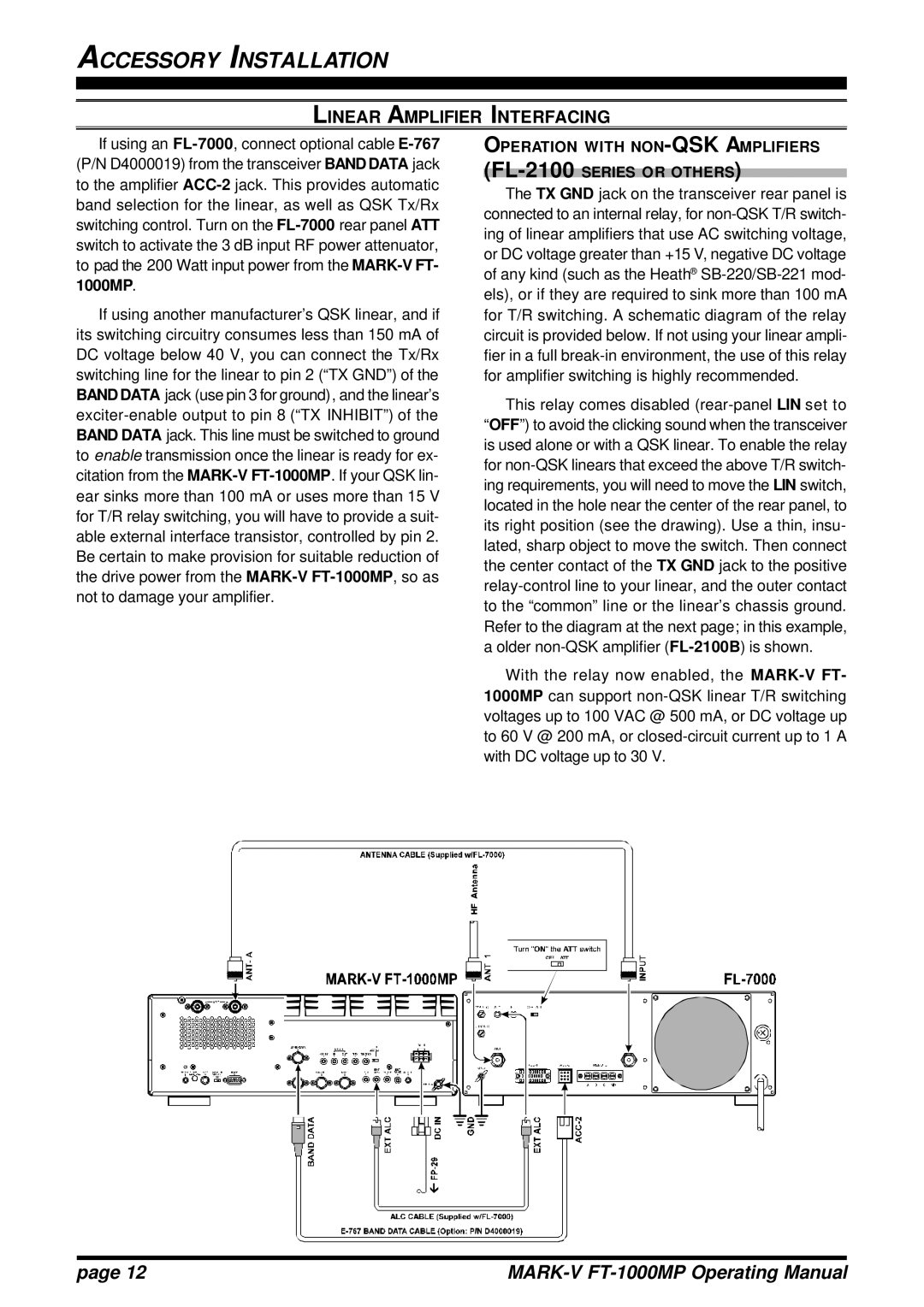
If using an FL-7000, connect optional cable E-767(P/N D4000019) from the transceiver BAND DATA jack to the amplifier ACC-2jack. This provides automatic band selection for the linear, as well as QSK Tx/Rx switching control. Turn on the FL-7000rear panel ATT switch to activate the 3 dB input RF power attenuator, to pad the 200 Watt input power from the MARK-V FT- 1000MP.

If using another manufacturer’s QSK linear, and if its switching circuitry consumes less than 150 mA of DC voltage below 40 V, you can connect the Tx/Rx switching line for the linear to pin 2 (“TX GND”) of the BAND DATA jack (use pin 3 for ground), and the linear’s exciter-enable output to pin 8 (“TX INHIBIT”) of the BAND DATA jack. This line must be switched to ground to enable transmission once the linear is ready for ex- citation from the MARK-VFT-1000MP. If your QSK lin- ear sinks more than 100 mA or uses more than 15 V for T/R relay switching, you will have to provide a suit- able external interface transistor, controlled by pin 2. Be certain to make provision for suitable reduction of the drive power from the MARK-VFT-1000MP, so as not to damage your amplifier.

OPERATION WITH NON-QSK AMPLIFIERS (FL-2100SERIES OR OTHERS)

The TX GND jack on the transceiver rear panel is connected to an internal relay, for non-QSK T/R switch- ing of linear amplifiers that use AC switching voltage, or DC voltage greater than +15 V, negative DC voltage of any kind (such as the Heath® SB-220/SB-221 mod- els), or if they are required to sink more than 100 mA for T/R switching. A schematic diagram of the relay circuit is provided below. If not using your linear ampli- fier in a full break-in environment, the use of this relay for amplifier switching is highly recommended.

This relay comes disabled (rear-panel LIN set to “OFF”) to avoid the clicking sound when the transceiver is used alone or with a QSK linear. To enable the relay for non-QSK linears that exceed the above T/R switch- ing requirements, you will need to move the LIN switch, located in the hole near the center of the rear panel, to its right position (see the drawing). Use a thin, insu- lated, sharp object to move the switch. Then connect the center contact of the TX GND jack to the positive relay-control line to your linear, and the outer contact to the “common” line or the linear’s chassis ground. Refer to the diagram at the next page; in this example, a older non-QSK amplifier (FL-2100B) is shown.

With the relay now enabled, the MARK-V FT- 1000MP can support non-QSK linear T/R switching voltages up to 100 VAC @ 500 mA, or DC voltage up to 60 V @ 200 mA, or closed-circuit current up to 1 A with DC voltage up to 30 V.

page 12

MARK-V FT-1000MP Operating Manual

Page 14
Image 14
Vertex Standard FT-1000MP manual Operation with NON-QSK Amplifiers FL-2100SERIES or Others