LCD BARGRAPH METER INDICATIONS
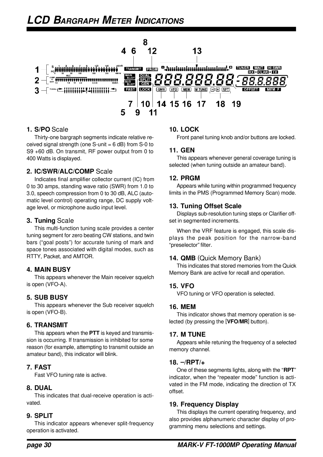
1.S/PO Scale
10. LOCK
Front panel tuning knob and/or buttons are locked.
11. GEN
This appears whenever general coverage tuning is selected (when tuning outside an amateur band).
2. IC/SWR/ALC/COMP Scale
Indicates final amplifier collector current (IC) from 0 to 30 amps, standing wave ratio (SWR) from 1.0 to 3.0, speech compression from 0 to 30 dB, ALC (auto- matic level control) operating range, DC supply volt- age level, or microphone audio input level.
3. Tuning Scale
This
4. MAIN BUSY
This appears whenever the Main receiver squelch is open
5. SUB BUSY
This appears whenever the Sub receiver squelch is open
6. TRANSMIT
This appears when the PTT is keyed and transmis- sion is occurring. If transmission is inhibited for some reason (for example, attempting to transmit outside an amateur band), this indicator will blink.
12. PRGM
Appears while tuning within programmed frequency limits in the PMS (Programmed Memory Scan) mode.
13. Tuning Offset Scale
Displays
When the VRF feature is engaged, this scale dis- plays the peak position for the
14.QMB (Quick Memory Bank)
This indicates that stored memories from the Quick Memory Bank are active for recall and operation.
15. VFO
VFO tuning or VFO operation is selected.
16. MEM
This indicator shows that memory operation is se- lected (by pressing the [VFO/MR] button).
17. M TUNE
Appears while retuning the frequency of a selected memory channel.
7. FAST
Fast VFO tuning rate is active.
8. DUAL
This indicates that
9. SPLIT
This indicator appears whenever
18. –/RPT/+
One of these segments lights, along with the “RPT” indicator, when the “repeater mode” function is acti- vated in the FM mode, indicating the direction of TX offset.
19. Frequency Display
This displays the current operating frequency, and also provides alphanumeric character display of pro- gramming menu selections and settings.
page 30 |
|