OPERATION
RECEIVING
ALTERNATE VFO OPERATION
(“FRONT & REAR•EVFO)
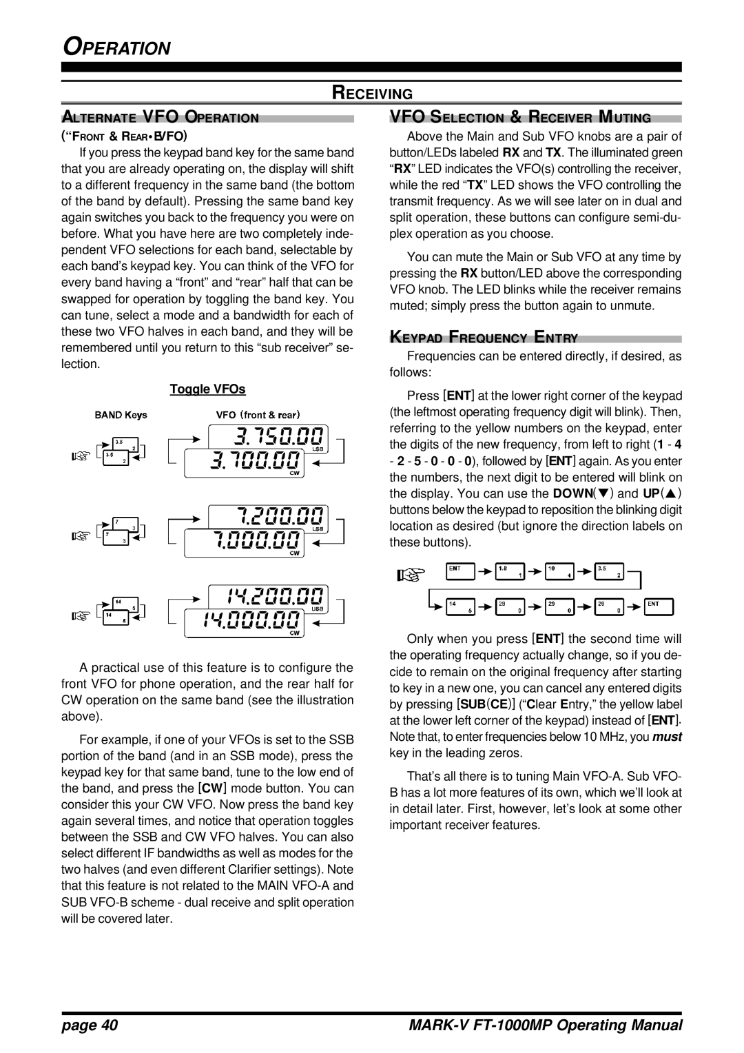
If you press the keypad band key for the same band that you are already operating on, the display will shift to a different frequency in the same band (the bottom of the band by default). Pressing the same band key again switches you back to the frequency you were on before. What you have here are two completely inde- pendent VFO selections for each band, selectable by each band’s keypad key. You can think of the VFO for every band having a “front” and “rear” half that can be swapped for operation by toggling the band key. You can tune, select a mode and a bandwidth for each of these two VFO halves in each band, and they will be remembered until you return to this “sub receiver” se- lection.
Toggle VFOs
VFO SELECTION & RECEIVER MUTING
Above the Main and Sub VFO knobs are a pair of button/LEDs labeled RX and TX. The illuminated green “RX” LED indicates the VFO(s) controlling the receiver, while the red “TX” LED shows the VFO controlling the transmit frequency. As we will see later on in dual and split operation, these buttons can configure
You can mute the Main or Sub VFO at any time by pressing the RX button/LED above the corresponding VFO knob. The LED blinks while the receiver remains muted; simply press the button again to unmute.
KEYPAD FREQUENCY ENTRY
Frequencies can be entered directly, if desired, as follows:
Press [ENT] at the lower right corner of the keypad (the leftmost operating frequency digit will blink). Then, referring to the yellow numbers on the keypad, enter the digits of the new frequency, from left to right (1 - 4
-2 - 5 - 0 - 0 - 0), followed by [ENT] again. As you enter the numbers, the next digit to be entered will blink on the display. You can use the DOWN(q) and UP(p) buttons below the keypad to reposition the blinking digit location as desired (but ignore the direction labels on these buttons).
A practical use of this feature is to configure the front VFO for phone operation, and the rear half for CW operation on the same band (see the illustration above).
For example, if one of your VFOs is set to the SSB portion of the band (and in an SSB mode), press the keypad key for that same band, tune to the low end of the band, and press the [CW] mode button. You can consider this your CW VFO. Now press the band key again several times, and notice that operation toggles between the SSB and CW VFO halves. You can also select different IF bandwidths as well as modes for the two halves (and even different Clarifier settings). Note that this feature is not related to the MAIN
Only when you press [ENT] the second time will the operating frequency actually change, so if you de- cide to remain on the original frequency after starting to key in a new one, you can cancel any entered digits by pressing [SUB(CE)] (“Clear Entry,” the yellow label at the lower left corner of the keypad) instead of [ENT]. Note that, to enter frequencies below 10 MHz, you must key in the leading zeros.
That’s all there is to tuning Main
page 40 |
|