OPERATION
RECEIVING
SIGNAL TUNING METER INDICATIONS
The
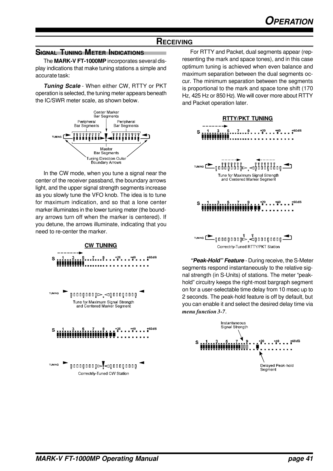
Tuning Scale - When either CW, RTTY or PKT operation is selected, the tuning meter appears beneath the IC/SWR meter scale, as shown below.
In the CW mode, when you tune a signal near the center of the receiver passband, the boundary arrows light, and the upper signal strength segments increase as you slowly tune the VFO knob. The idea is to tune for maximum indication, and so that a lone center marker illuminates in the lower tuning meter (the bound- ary arrows turn off when the marker is centered). If you detune, the arrows illuminate, indicating that you need to
CW TUNING
For RTTY and Packet, dual segments appear (rep- resenting the mark and space tones), and in this case optimum tuning is achieved when even balance and maximum separation between the dual segments oc- cur. The minimum separation between the segments is proportional to the mark and space tone shift (170 Hz, 425 Hz or 850 Hz). We will cover more about RTTY and Packet operation later.
RTTY/PKT TUNING
| page 41 |