LCD BARGRAPH METER INDICATIONS
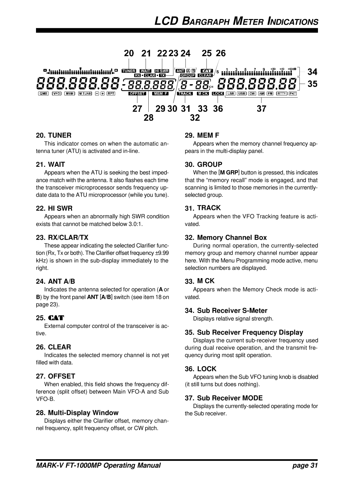
20. TUNER
This indicator comes on when the automatic an- tenna tuner (ATU) is activated and
29. MEM F
Appears when the memory channel frequency ap- pears in the
21. WAIT
Appears when the ATU is seeking the best imped- ance match with the antenna. It also flashes each time the transceiver microprocessor sends frequency up- date data to the ATU microprocessor (while you tune).
22. HI SWR
Appears when an abnormally high SWR condition exists that cannot be matched below 3.0:1.
23. RX/CLAR/TX
These appear indicating the selected Clarifier func- tion (Rx, Tx or both). The Clarifier offset frequency ±9.99 kHz) is shown in the
24. ANT A/B
Indicates the antenna selected for operation (A or B) by the front panel ANT [A/B] switch (see item 18 on page 23).
25.CAT
External computer control of the transceiver is ac- tive.
26. CLEAR
Indicates the selected memory channel is not yet filled with data.
27. OFFSET
When enabled, this field shows the frequency dif- ference (split offset) between Main
28. Multi-Display Window
Displays either the Clarifier offset, memory chan- nel frequency, split frequency offset, or CW pitch.
30. GROUP
When the [M GRP] button is pressed, this indicates that the “memory recall” mode is engaged, and that scanning is limited to those memories in the currently- selected group.
31. TRACK
Appears when the VFO Tracking feature is acti- vated.
32. Memory Channel Box
During normal operation, the
33. M CK
Appears when the Memory Check mode is acti- vated.
34. Sub Receiver S-Meter
Displays relative signal strength.
35. Sub Receiver Frequency Display
Displays the current
36. LOCK
Appears when the Sub VFO tuning knob is disabled (it still turns but does nothing).
37. Sub Receiver MODE
Displays the
| page 31 |