OPERATION
TRANSMITTING
If the SWR presented to the transceiver is above 3:1, the tuner will generally not complete the tuning process (although in certain borderline cases, it may actually be able to lower the SWR below 1.5:1). If the
After using the antenna tuner, the “TUNER” indica- tor will remain on (unless you press the [TUNER] but- ton to turn it off), and the “WAIT” indicator will flicker momentarily when you change frequency, indicating that the main microprocessor is reporting the frequency change to the tuner coprocessor (reception is unaf- fected). If you have tuned far enough to possibly re- quire rematching, it will reset itself to the new range (if it has any previously stored settings for the new range). However, when you first connect a new antenna, the tuner will not have the correct settings stored in these memories, so you will need to “train” the tuner, by press- ing and holding the [TUNER] button for ½ second when- ever you change to a new band or frequency range (for this antenna).
If you want to use an external antenna tuner, the internal ATU should be disabled. menu selection
Note: The “G5RV” multiband antenna does not present an SWR below 3:1 on all HF amateur bands, despite its reputation as an
SSB TRANSMISSION
To transmit in LSB or USB mode:
rMake sure the appropriate mode indicator is lit, and set the meter ALC/COMP selector to view “ALC.”
rIf this is the first time you are transmitting SSB with the
rCheck the “RX” and “TX” LEDs above the tuning knobs to determine which frequency you’re going to transmit on, and make sure “GEN” is not show- ing to the left of the main frequency display.
rTo transmit, just press the PTT
To determine the optimum setting of the MIC con- trol for your microphone, adjust it while speaking into the microphone (at a normal level) so that the meter deflects to about midrange on voice peaks (the upper end of the red ALC range). Once found, this setting can be left
You can adjust the RF PWR control for more or less output, from about 5 to 200 watts (on the upper PO meter scale), as desired. However, you should al- ways use the lowest possible power output to maintain reliable communications - not only as a courtesy to other stations, but to minimize the possibility of caus- ing overload to nearby
Important Note
Although the antenna tuning process normally is very fast, certain difficult impedances may require as long as 50 seconds to match. This is a normal condition, however, related to the time required for the variable capacitors to make a complete search for the optimum setting with the available values of inductance.
Transmitter Monitor
The transmitter monitor is actually a separate re- ceiver circuit which picks up a sample of your trans- mitted RF signal, allowing you to hear accurately how the signal sounds. This feature is very helpful for set- ting up the speech processor controls, among other things.
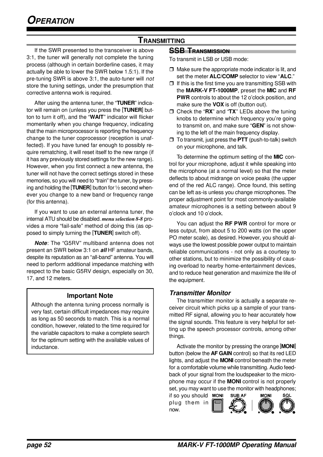
Activate the monitor by pressing the orange [MONI] button (below the AF GAIN control) so that its red LED lights, and adjust the MONI control beneath the meter for a comfortable volume while transmitting. Audio feed- back of your signal from the loudspeaker to the micro- phone may occur if the MONI control is not properly set, you may want to use the monitor with headphones; if so you should ![]()
![]()
![]()
![]()
![]()
![]()
![]()
![]()
![]() p l u g t h e m i n
p l u g t h e m i n ![]()
![]()
![]()
![]()
![]()
![]()
![]()
![]()
![]()
![]()
![]()
![]()
![]()
![]()
![]()
![]()
![]()
![]()
![]()
![]()
![]()
![]()
![]() now.
now.![]()
![]()
![]()
![]()
![]()
![]()
![]()
![]()
![]()
![]()
![]()
![]()
![]()
![]()
![]()
![]()
![]()
![]()
![]()
![]()
![]()
![]()
![]()
![]()
![]()
![]()
![]()
page 52 |
|