CAT System Computer Control
16-BYTE DATA RECORD STRUCTURE
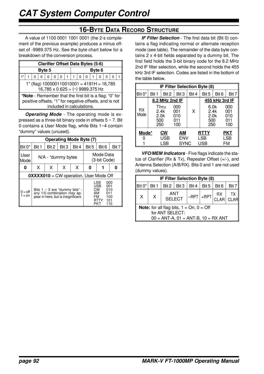
A value of 1100 0001 1001 0001 (the
Clarifier Offset Data Bytes (5-6)
|
|
| Byte 5 |
|
|
|
|
|
|
|
|
|
|
| Byte 6 |
|
|
|
|
|
| ||||||
1* |
| 0 |
| 0 |
| 0 |
| 0 |
| 0 |
| 1 | 1 |
| 0 |
| 0 |
| 1 |
| 0 |
| 0 |
| 0 |
| 1 |
1 |
|
|
|
|
|
|
|
|
|
|
|
| |||||||||||||||
|
|
|
|
|
|
|
|
|
|
|
|
|
|
|
|
|
|
|
|
|
|
|
|
|
|
|
|
1* (flag) 100000110010001 = 4191H = 16,785
16,785 x 0.625 =
*Note - Remember that the first bit is a flag: “0” for positive offsets, “1” for negative offsets, and is not included in calculations.
Operating Mode - The operating mode is ex- pressed as a
Operating Mode Byte (7)
Bit 0* | Bit 1 | Bit 2 | Bit 3 | Bit 4 | Bit 5 | Bit 6 | Bit 7 | ||
User | N/A - “dummy bytes | Mode Data | |||||||
Mode | |||||||||
|
|
|
| ||||||
0 | X | X | X | X | 0 | 1 |
| 0 | |
|
|
|
|
|
|
|
| ||
0XXXX010 = CW operation, User Mode Off | |||||||||
|
|
|
|
|
|
|
|
| |
|
|
|
|
| LSB | 000 | |||
|
|
|
|
| USB | 001 | |||
0 = off | Bits 1 ~ 3 are “dummy bits” - | CW | 010 | ||||||
any 1/0 combination may ap- | AM | 011 | |||||||
1 = on | |||||||||
pear in here, but is insignificant. | FM | 100 | |||||||
|
|
|
|
| RTTY | 101 | |||
|
|
|
|
| PKT | 110 | |||
IF Filter Selection - The first data bit (Bit 0) con- tains a flag indicating normal or alternate reception mode (see table). The remainder of the data byte con- tains 2 x
IF Filter Selection Byte (8)
Bit 0* | Bit 1 | Bit 2 |
| Bit 3 | Bit 4 | Bit 5 | Bit 6 |
| Bit 7 |
| 8.2 MHz 2nd IF |
| 455 kHz 3rd IF | ||||||
RX | Thru | 000 |
| 6.0k | 000 | ||||
2.4k | 001 | X | 2.4k | 001 | |||||
Mode | 2.0k | 010 |
| 2.0k | 010 | ||||
| 500 | 011 |
| 500 | 011 | ||||
| 250 | 100 |
| 250 | 100 | ||||
Mode* | CW | AM | RTTY | PKT |
0 | USB | ENV | LSB | LSB |
1 | LSB | SYNC | USB | FM |
VFO/MEM Indicators - Five flags indicate the sta- tus of Clarifier (Rx & Tx), Repeater Offset
|
| IF Filter Selection Byte (8) |
|
| |||||
Bit 0* | Bit 1 |
| Bit 2 | Bit 3 | Bit 4 | Bit 5 |
| Bit 6 | Bit 7 |
X | X |
| ANT | +RPT |
| RX | TX | ||
| SELECT |
| CLAR | CLAR | |||||
|
|
|
|
|
|
|
|
|
|
Note: for all flag bits, 1 = On, 0 = Off for ANT SELECT:
00 =
page 92 |
|
