GENERAL SETUP

ANTENNA CONSIDERATIONS

The MARK-VFT-1000MPis designed for use with any antenna system providing a 50 Ω resistive imped- ance at the desired operating frequency. While minor excursions from the 50 Ω specification are of no con- sequence, the transceiver’s Automatic Antenna Tuner may not be able to reduce the impedance mismatch to an acceptable value if the Standing Wave Ratio (SWR) present at the Antenna jack is greater than 3:1. Among the undesirable consequences that high SWR may produce are:

rThe transceiver’s power amplifier protection circuitry will reduce power if the Automatic Antenna Tuner is unsuccessful in reducing the SWR.

rEven if the Automatic Antenna Tuner successfully normalizes the impedance presented to the radio, feedline losses will escalate rapidly with increasing SWR at the higher operating frequencies, especially 28 MHz.

rAlthough high SWR itself does not cause feedline radiation, the sudden onset of high SWR may well indicate a mechanical failure in a matching device, leading to an electrical condition which may cause excessive feedline radiation, which can cause in- terference to nearby home-entertainment devices.

Every effort should, therefore, be made to ensure that the impedance of the antenna system utilized with the MARK-VFT-1000MPbe as close as possible to the specified 50 Ω value.

Any antenna to be used with the MARK-V FT- 1000MP must, ultimately, be fed with 50 Ω coaxial cable. Therefore, when using a “balanced” antenna such as a dipole, remember that a balun or other match- ing/balancing device must be used so as to ensure proper antenna performance.

The same precautions apply to any additional (re- ceive-only) antennas connected to the RX ANT jack; if your receive-only antennas do not have an impedance near 50 Ω at the operating frequency, you may need to install an external antenna tuner to obtain optimum performance.

Loss in dB per 30m (100 feet) for Selected 50 Ω Coaxial Cables

(Assumes 50 Ω Input/Output Terminations)


Cable Type

Loss:

Loss:

Loss:


2 MHz

15 MHz

28 MHz


RG-58A

0.55

1.75

2.60


RG-58 Foam

0.54

1.50

2.00


RG-8X

0.39

1.07

1.85


RG-8A, RG-213

0.27

0.85

1.25


RG-8 Foam

0.22

0.65

0.88


Belden® 9913

0.18

0.50

0.69


RG-17A

0.88

0.30

0.46


Loss figures are approximate; consult cable manufac- turers’ catalogs for complete specifications.

Loss figures can increase significantly if high SWR is present on the transmission line.

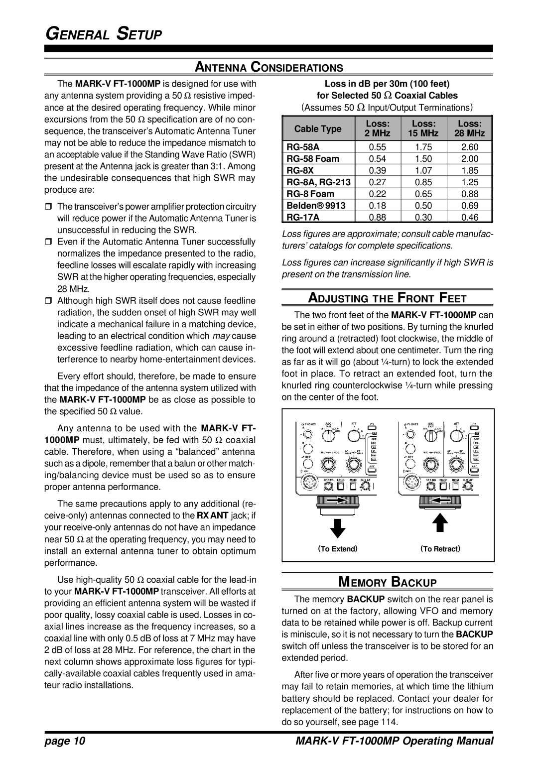
ADJUSTING THE FRONT FEET

The two front feet of the MARK-VFT-1000MPcan be set in either of two positions. By turning the knurled ring around a (retracted) foot clockwise, the middle of the foot will extend about one centimeter. Turn the ring as far as it will go (about ¼-turn) to lock the extended foot in place. To retract an extended foot, turn the knurled ring counterclockwise ¼-turn while pressing on the center of the foot.

(To Extend)

(To Retract)

Use high-quality 50 Ω coaxial cable for the lead-in to your MARK-VFT-1000MPtransceiver. All efforts at providing an efficient antenna system will be wasted if poor quality, lossy coaxial cable is used. Losses in co- axial lines increase as the frequency increases, so a coaxial line with only 0.5 dB of loss at 7 MHz may have 2 dB of loss at 28 MHz. For reference, the chart in the next column shows approximate loss figures for typi- cally-available coaxial cables frequently used in ama- teur radio installations.

MEMORY BACKUP

The memory BACKUP switch on the rear panel is turned on at the factory, allowing VFO and memory data to be retained while power is off. Backup current is miniscule, so it is not necessary to turn the BACKUP switch off unless the transceiver is to be stored for an extended period.

After five or more years of operation the transceiver may fail to retain memories, at which time the lithium battery should be replaced. Contact your dealer for replacement of the battery; for instructions on how to do so yourself, see page 114.

page 10

MARK-V FT-1000MP Operating Manual

Page 12
Image 12
Vertex Standard FT-1000MP manual Antenna Considerations, Adjusting the Front Feet, Memory Backup, RG-8X